<?xml version="1.0" encoding="utf-8"?><feed xmlns="http://www.w3.org/2005/Atom" ><generator uri="https://jekyllrb.com/" version="3.10.0">Jekyll</generator><link href="http://www.buffee.ca/feed.xml" rel="self" type="application/atom+xml" /><link href="http://www.buffee.ca/" rel="alternate" type="text/html" /><updated>2026-07-02T04:53:29+00:00</updated><id>http://www.buffee.ca/feed.xml</id><title type="html">The Buffee Project</title><subtitle>Home of the new 68K (and other stuff)</subtitle><author><name>Renee Cousins</name></author><entry><title type="html">Scanlines Fixed</title><link href="http://www.buffee.ca/scanlines/" rel="alternate" type="text/html" title="Scanlines Fixed" /><published>2026-07-01T00:00:00+00:00</published><updated>2026-07-01T00:00:00+00:00</updated><id>http://www.buffee.ca/scanlines</id><content type="html" xml:base="http://www.buffee.ca/scanlines/"><![CDATA[<p>Oh how I've seen my share of bad scalars for old 2D games – from exaggerated CRT effects that make me feel as though I'm on LSD to interpolation routines that make every game look like its made with papercraft. Old school computers present a problem when being displayed on modern televisions that have resolutions significantly higher than the source material. Today, I provide my solution for this.</p>

<p>I want to start with the output:
<img src="/images/Flashback_Anim.png" alt="image" />
￼
My scanlines achieve three important things</p>
<ul>
  <li>they can correct for any aspect ratio</li>
  <li>they show the artwork in the manner it was intended</li>
  <li>they do <strong>NOT</strong> dim the image</li>
</ul>

<p>And it's that last one that actually helps enhance detail, bring back some of the image lost in the murkiness of the dark greys and browns. The warning stripes look like diagonal lines now, not staircases and the vines wrap around and look more organic, not like they're made from LEGO.</p>

<p>And the weird thing is that this is not mathematically hard to achieve and can be used for any mask effect, not just scanlines. Want a Sony Triniton look instead? This algorithm will still work and you'll still get full brigness on your screen without fakery like bloom, pushing brightness or, god forbid, injecting HDR.</p>

<p>The rules are simple.</p>

<h2 id="1-integer-vertical-scaling">1. Integer Vertical Scaling</h2>

<p>This algorithm can scale from 2x up; there's no practical limit, but it's important that vertical scaling is always in integer increments. This is not widely disputed anymore, so I'll move on.</p>

<h2 id="2-bilinear-horizontal-scaling">2. Bilinear Horizontal Scaling</h2>

<p>On the Amiga, as an example, PAL and NTSC were not square pixels and regardless of which one you grew up with, modern displays using integer scaling in BOTH directions WILL get this wrong. This is an image of Workbench 2.0 correctly adjusted for PAL. To achieve this, the horizontal resolution needs to be pushed out slightly to 1,332 pixels instead of 1,280.</p>

<p><img src="/images/Workbench_KSL_PAL_Correct.png" alt="image" /></p>

<p>This looks so right to me, I can taste the nostalgia.</p>

<h2 id="3-preserve-the-brightness">3. Preserve the Brightness</h2>

<p>The average of the bright and dark lines should always equal the colour of the original image. To achieve this simply we use two transfer functions converting the input RGB to the output RGB we display.</p>

<h3 id="dark-lines">Dark Lines</h3>

<p>For dark lines, we output each channel as a simple C' = MAX(0, C * 2 - 255). In Verilog this looks like:</p>
<pre><code class="language-v">red_out &lt;= { t_red[2:0], 1'b1 } &amp; {4{t_red[3]}};
grn_out &lt;= { t_grn[2:0], 1'b1 } &amp; {4{t_grn[3]}};
blu_out &lt;= { t_blu[2:0], 1'b1 } &amp; {4{t_blu[3]}};
</code></pre>
<p>And maps like this:</p>
<div class="language-plaintext highlighter-rouge"><div class="highlight"><pre class="highlight"><code>OUT
 F                               *
 E                               
 D                             * 
 C                               
 B                           *   
 A                               
 9                         *     
 8                               
 7                       *       
 6                               
 5                     *         
 4                               
 3                   *           
 2                               
 1                 *             
 0 * * * * * * * *               
   0 1 2 3 4 5 6 7 8 9 A B C D E F	IN
</code></pre></div></div>
<h3 id="light-lines">Light Lines</h3>

<p>For light lines, we output each channel as a simple C' = MIN(255, C * 2). In Verilog this looks like:</p>
<pre><code class="language-v">red_out &lt;= { t_red[2:0], 1'b0 } | {4{t_red[3]}};
grn_out &lt;= { t_grn[2:0], 1'b0 } | {4{t_grn[3]}};
blu_out &lt;= { t_blu[2:0], 1'b0 } | {4{t_blu[3]}};
</code></pre>
<p>And maps like this:</p>
<div class="language-plaintext highlighter-rouge"><div class="highlight"><pre class="highlight"><code>OUT
 F                 * * * * * * * *
 E               *                
 D                                
 C             *                  
 B                                
 A           *                    
 9                                
 8         *                      
 7                                
 6       *                        
 5                                
 4     *                          
 3                                
 2   *                            
 1                                
 0 *                              
   0 1 2 3 4 5 6 7 8 9 A B C D E F	IN
</code></pre></div></div>

<h2 id="final-thoughts">Final Thoughts</h2>

<p>It's odd how much better everything looks dispite this not being a "true" CRT filter. It's nice not losing brightness on a display technology that today still struggles to achieve the same room-filling illumination of a CRT, so why make it worse. This isn't something that takes a lot of math or filtering and would add absolutely no delay to the pixel pipeline. On something like a RetroTINK, you would not have any change in the latency.</p>

<p>I've already implemented this on my fork of MiniMig which I'll be putting up on github shortly. I've also fixed Paula to return her to her crunchy glory and fixed some of the more eggregious wastes of FPGA logic, in part, thanks to the Lisa schematics. At least one mystery was solved – how the colour table works on Denise. No it's not dual ported, and no it's not banked.</p>

<p>Anyway, cheers and next post will be an update on Buffee. I have thoughts on that, too.</p>]]></content><author><name>Renee Cousins</name></author><summary type="html"><![CDATA[Oh how I've seen my share of bad scalars for old 2D games – from exaggerated CRT effects that make me feel as though I'm on LSD to interpolation routines that make every game look like its made with papercraft. Old school computers present a problem when being displayed on modern televisions that have resolutions significantly higher than the source material. Today, I provide my solution for this.]]></summary></entry><entry><title type="html">A Little Note on 5V FPGA</title><link href="http://www.buffee.ca/on-5v-fpga/" rel="alternate" type="text/html" title="A Little Note on 5V FPGA" /><published>2026-02-25T00:00:00+00:00</published><updated>2026-02-25T00:00:00+00:00</updated><id>http://www.buffee.ca/on-5v-fpga</id><content type="html" xml:base="http://www.buffee.ca/on-5v-fpga/"><![CDATA[<p>There's a persistent myth in the electronics commnity that if you want programmable logic to interface with 5V these days you have two options – very old CPLDs (Complex Programmable Logic Devices) or use level shifters to convert the 5V down to 3.3V as there are no 5V FPGA anymore. Well, I'd like to spend a few minutes busting this myth.</p>

<h2 id="level-shifters">Level Shifters</h2>

<p>A quick aside, if you need level shifters or feel safer with them, then that's fine, I'm not at all condemning their use. And I would like to give a huge shout out to the A314 project that proved that the CBT(D) devices are absolutely fine for anything 5V TTL. This is because 5V TTL is designed to respond to a high logic level as low as 2.0V which also fits nicely within the range for 3.3V CMOS devices.</p>

<h2 id="true-5v-fpga">True 5V FPGA</h2>

<p>So lets get this out of the way right now – there is a true 5V FPGA on the market and it's a pretty great chip. The AT40K series has been in production now since 1997 and as with their PIC microcontrollers, Microchip seems hell bent on never deprecating these parts. The largest of these is the AT40K40 with up to 384 IO pins, 18Kbit of internal RAM and 2,304 logic cells, but even the smallest, the AT40K10 with only 576 cells has VASTLY more logic room than even the largest CPLD.</p>

<p>It's interestingly difficult to just "browse" to these from Microchips website though, so I've included links.</p>

<table>
  <thead>
    <tr>
      <th>Part</th>
      <th style="text-align: center">Logic<br />Cells</th>
      <th style="text-align: center">RAM<br />(Kbit)</th>
      <th style="text-align: center">AVR</th>
    </tr>
  </thead>
  <tbody>
    <tr>
      <td><a href="https://www.microchip.com/en-us/product/at40k10">AT40K10(LV)</a><a href="https://www.microchip.com/en-us/product/at40k10al">/(AL)</a></td>
      <td style="text-align: center">576</td>
      <td style="text-align: center">4.5</td>
      <td style="text-align: center">No</td>
    </tr>
    <tr>
      <td><a href="https://www.microchip.com/en-us/product/at40k20">AT40K20(LV)</a><a href="https://www.microchip.com/en-us/product/at40k20">/(AL)</a></td>
      <td style="text-align: center">1024</td>
      <td style="text-align: center">8</td>
      <td style="text-align: center">No</td>
    </tr>
    <tr>
      <td><a href="https://www.microchip.com/en-us/product/at40k40">AT40K40(LV)</a><a href="https://www.microchip.com/en-us/product/at40k40">/(AL)</a></td>
      <td style="text-align: center">2304</td>
      <td style="text-align: center">18</td>
      <td style="text-align: center">No</td>
    </tr>
    <tr>
      <td><a href="/images/AT94K_FPSLIC.PDF">AT94K05AL</a></td>
      <td style="text-align: center">576</td>
      <td style="text-align: center">4.5</td>
      <td style="text-align: center">25MHz</td>
    </tr>
    <tr>
      <td><a href="/images/AT94K_FPSLIC.PDF">AT94K10AL</a></td>
      <td style="text-align: center">1024</td>
      <td style="text-align: center">8</td>
      <td style="text-align: center">25MHz</td>
    </tr>
    <tr>
      <td><a href="/images/AT94K_FPSLIC.PDF">AT94K40AL</a></td>
      <td style="text-align: center">2304</td>
      <td style="text-align: center">18</td>
      <td style="text-align: center">25MHz</td>
    </tr>
    <tr>
      <td><a href="/images/AT94K_FPSLIC.PDF">AT94S05AL</a></td>
      <td style="text-align: center">576</td>
      <td style="text-align: center">4.5</td>
      <td style="text-align: center">40MHz</td>
    </tr>
    <tr>
      <td><a href="/images/AT94K_FPSLIC.PDF">AT94S10AL</a></td>
      <td style="text-align: center">1024</td>
      <td style="text-align: center">8</td>
      <td style="text-align: center">40MHz</td>
    </tr>
    <tr>
      <td><a href="/images/AT94K_FPSLIC.PDF">AT94S40AL</a></td>
      <td style="text-align: center">2304</td>
      <td style="text-align: center">18</td>
      <td style="text-align: center">40MHz</td>
    </tr>
  </tbody>
</table>

<p>They even have features few other FPGA have:</p>
<ul>
  <li>partial reconfigurability (they call caching)</li>
  <li>highly configurable IO with delay/slew</li>
  <li>the 's' variants include configuration ROM on-chip</li>
</ul>

<p>Its logic cells are not directly comparable to other FPGA chips (whose are?) with two 3-input LUTs that can be chained into one 4-input LUT, includes the very common DFF with tri-state output and internal feedback, internal 2-to-1 mux and hard AND gate for efficient multipliers.</p>

<p>But a modern FPGA it is not. Propagation delays in-fabric are pretty high compared to modern logic. It's large enough and fast enough though to be a great bus-bridge or maybe even a simple microprocessor. As with any FPGA these days, it supports VHDL and Verilog, so it's just a matter of remapping the pins.</p>

<p>So there … there's a real, bona-fide 5V FPGA that's still in production.</p>

<p>Note: The LV and AL are not marketted as "true" 5V, they are 3.3V devices but remain 5V "tolerant." What this means is that the <strong><em>output</em></strong> of the IO is 0~3.3V but the input can safely tolerate 5.0V levels. So quite literally, it's "tolerant" of 5V parts, but is not, itself, 5V anymore. That's fine, because 5V TTL does not need "true" 5V outputs.</p>

<p>However, in the datasheets, the absolute maximum for the voltage is still listed at 7.0V which means in actuality, these are still 5V parts. Even the FPSLIC (with AVR microntroller) list 5.5V as the maximum for input voltage, so yes, even it is a 5V part – with the caveat that the AVR operates faster with lower voltages – you probably won't get 25MHz above 3.3V.</p>

<h2 id="a-modern-alternative">A Modern Alternative</h2>

<p>The iCE40 is the successor to the iCE65 P series from SiliconBlue which was marketted as 5V tolerant. There is no clear evidence that the iCE40 was ever intended to also be 5V tolerant, however, in 2021 it was discovered quite by accident that the iCE40 HX <strong><em>might be</em></strong>. When interfacing with a PS2 keyboard, it was discovered that the iCE40 did not, in fact, release the magic smoke when absent of any external current limiting resistors.</p>

<p>With a 47K series resistors the following was observed.</p>

<table>
  <thead>
    <tr>
      <th>Source<br />Voltage</th>
      <th style="text-align: right">Pin<br />Voltage</th>
      <th style="text-align: right">Leakage<br />Current</th>
    </tr>
  </thead>
  <tbody>
    <tr>
      <td>5.0V</td>
      <td style="text-align: right">5.00V</td>
      <td style="text-align: right">0</td>
    </tr>
    <tr>
      <td>6.0V</td>
      <td style="text-align: right">6.03V</td>
      <td style="text-align: right">550nA</td>
    </tr>
    <tr>
      <td>6.5V</td>
      <td style="text-align: right">6.35V</td>
      <td style="text-align: right">3uA</td>
    </tr>
    <tr>
      <td>8.0V</td>
      <td style="text-align: right">6.39V</td>
      <td style="text-align: right">34uA</td>
    </tr>
    <tr>
      <td>10V</td>
      <td style="text-align: right">6.40V</td>
      <td style="text-align: right">77uA</td>
    </tr>
    <tr>
      <td>20V</td>
      <td style="text-align: right">6.41V</td>
      <td style="text-align: right">290uA</td>
    </tr>
  </tbody>
</table>

<p>It should be noted that 20V is already in the realm of "distructive testing" for any 3.3V part.</p>

<h3 id="document-archaeology">Document Archaeology</h3>

<p>There is no record of any <a href="/images/iCE40HX_Rev120330.pdf">iCE40 datasheet prior to 1.31</a>, even on the Wayback Machine and there is no mention of 5V tolerance there or on any of SiliconBlue's saved webpages from the era. There are some interesting things to note though; there are signs this information was scrubbed and 1.31 shows this – in progress – as it contains mention of JTAG which was removed in all later literature from Lattice and has a weirdly-round 4.00V as the absolute maximum they later nerf further to the more "common" 3.60V found with 3.3V logic.</p>

<p>Hmmm…</p>

<p>The IO structure is identical as all the drawings are directly ripped from earlier SiliconBlue drawings and it's probable they used the same macro cells. It's worth adding that TSMC's 40nm process likely has the same 5-7nm thick oxide layer, so 5V tolerance is likely.</p>

<h3 id="why-would-they">Why Would They?</h3>

<p>I mean, this is pure speculation and there's a lot of conspiracy theories out there as other manufacturers have pulled 5V tolerance for a number of reasons from not wanting to look antiquated, confusion over "real" 5V parts and 5V "tolerance" as well as the additional burden of testing.</p>

<p>However, I think the reason is actually simpler and more obvious – temperature range.</p>

<p>The iCE40 is marketted as a mobile FPGA and supports an impressive 125°C junction temperature tolerance. It can get pretty roasty inside of those smartphones and tables with little-to-no ventilation, and 5V would absolutely bring that maximum down.</p>

<p>For retro use, that doesn't matter.</p>

<h2 id="the-pudding">The Pudding</h2>

<h3 id="1-faith">1. Faith</h3>

<p>A while back, Kipper2K and I worked on the Amiga Replacement Project and came up with a versatile DIP-sized board that could replace any 40 or 48-pin DIP chip with little modification. He put together a couple of Faith board (Denise replacements) before disappearing.</p>

<p><img src="/images/FaithInTesting.jpg" alt="" /></p>

<p>In the interest of testing, the first step was actually implementing Denise into FPGA. On January 3, 2026, I got the first good output from my CDTV. Well tickle me gingers.</p>

<p><img src="/images/CDTV_boot.gif" alt="" /></p>

<p>I was worried that maybe it would be darker or something, but nah, this looks fantastic. It's not the best code and it was horribly broken when trying some demos, but it proved the case. I've put all the code over in the Amiga Replacement Project repository, but at the moment, it's not 100% Super Denise compatible and there's a bug in the board that has disabled the on-board Flash.</p>

<p>Side note: I'm really impressed with yosys/icestorm.</p>

<p>It's been running on and off now for over a month with no degradation, but this isn't proof that it'll last, that's going to take more work.</p>

<h3 id="2-destructive-testing">2. Destructive Testing</h3>

<p>I recently managed to get a bunch of equipment to start making some boards myself. One of these was a hot plate and that got me thinking – I could put my 500+ upside down on there and cook it at 80°C for a few days straight and then redo the original current test. If the pin was degraded in anyway, we should see more leakage; i.e., more current being drawn or a lower voltage limit.</p>

<p>I'll need to set up a little Linux server to do this though, since, because of the bug, the moment I unplug my MacBook, Faith will reset and then clear it's config.</p>

<p>This should prove whether the part is really 5V tolerant or not. I personally believe it will be a huge boon to the retro community at large if this works; this  reduces parts, board complexity and size, making these little DIP and PLCC inside boards possible.</p>

<p>I'll post here when this is done.</p>]]></content><author><name>Renee Cousins</name></author><summary type="html"><![CDATA[There's a persistent myth in the electronics commnity that if you want programmable logic to interface with 5V these days you have two options – very old CPLDs (Complex Programmable Logic Devices) or use level shifters to convert the 5V down to 3.3V as there are no 5V FPGA anymore. Well, I'd like to spend a few minutes busting this myth.]]></summary></entry><entry><title type="html">Back to Buffee Full Time!</title><link href="http://www.buffee.ca/back-to-fulltime/" rel="alternate" type="text/html" title="Back to Buffee Full Time!" /><published>2024-07-09T00:00:00+00:00</published><updated>2024-07-09T00:00:00+00:00</updated><id>http://www.buffee.ca/back-to-fulltime</id><content type="html" xml:base="http://www.buffee.ca/back-to-fulltime/"><![CDATA[<p>Well, I was laid off. But what sucks for me will be a win for the community as I'm working on Buffee again full-time, and progress has been … interesting. We're also really happy to see prices falling on some of the critical parts of our BOM, especially the main microprocessor. So how about a little "State of the Union Address?"</p>

<table>
  <thead>
    <tr>
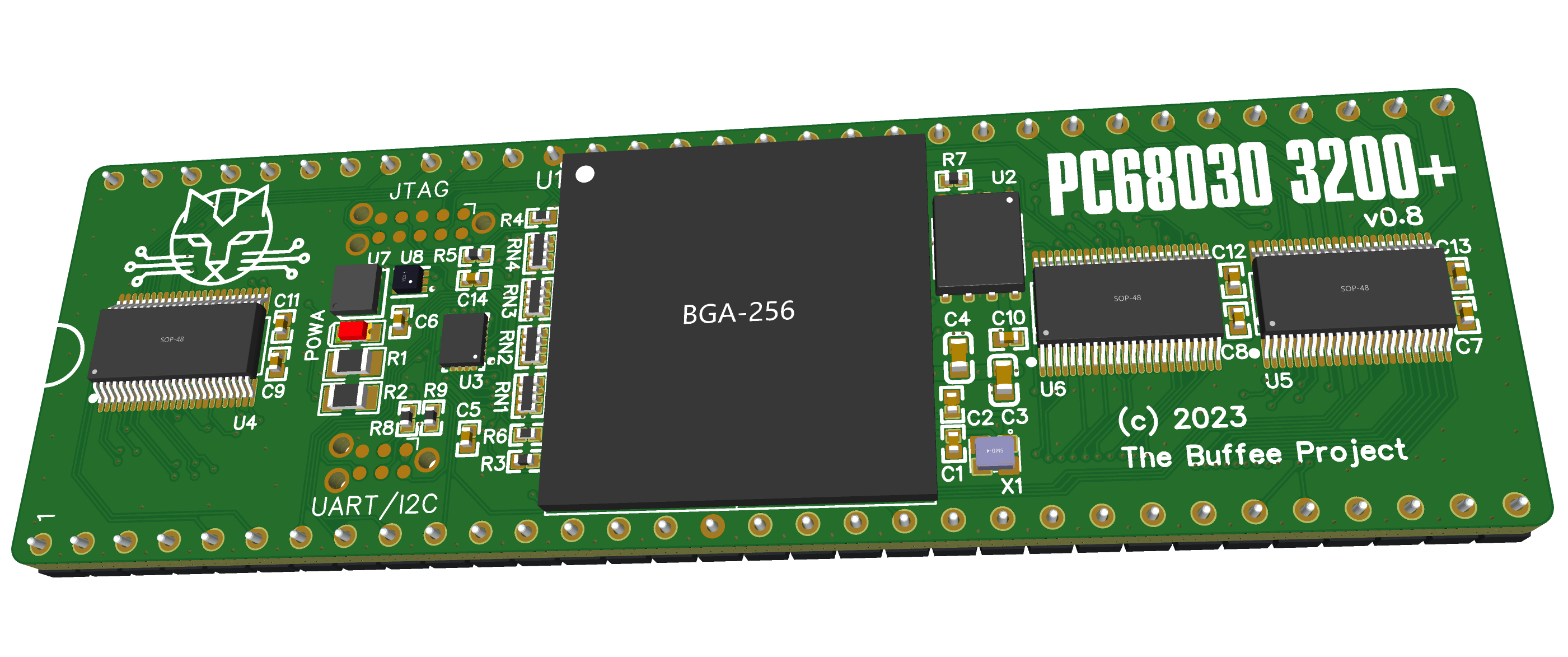
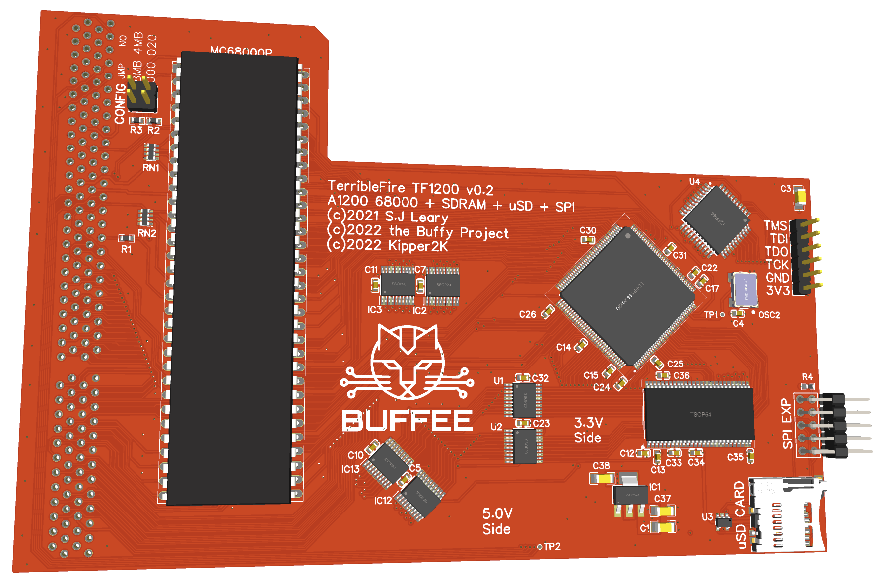
      <th style="text-align: center"><img src="https://raw.githubusercontent.com/lostcatproductions/lostcatproductions.github.io/master/images/Buffee_v0.8_render.png" alt="How low can you go?" /></th>
    </tr>
  </thead>
  <tbody>
    <tr>
      <td style="text-align: center">Are we there yet Papa Smurf?</td>
    </tr>
  </tbody>
</table>

<p>We can read chip RAM at 100% if we "cheat". Our error rate was as low as 2 errors per 25,600 reads, but that's enough to crash any computer within microseconds of booting. However, there's an old trick I used back in my firmware days of debouncing with three reads – basically it's <code class="language-plaintext highlighter-rouge">(A&amp;B)|(A&amp;C)|(B&amp;C)</code>. As long as the bits are right 2 of the 3 times, and we don't see any sort of "clustering" with the read/write errors then we should be good. And so far we are.</p>

<p>Is it fast? Nope. Does it work? Yeah.</p>

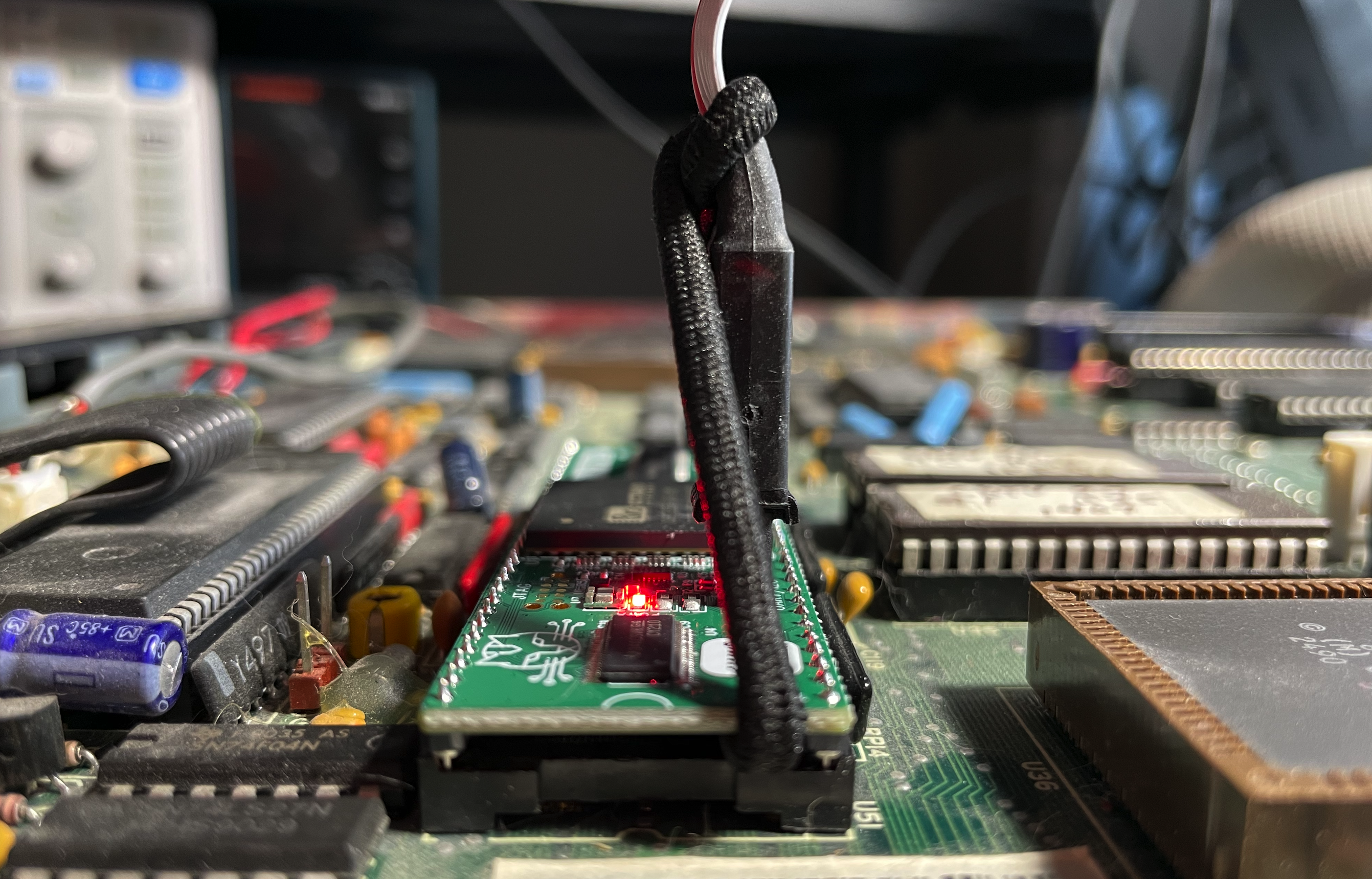
<p>Our immediate goal now is to simply show it running at all and we're very, very close. The outstanding issue seems to be with interrupts and weird gremlins I thought might have been because of my CDTV relic. However, it turns out the CDTV is fine (yay!) and it was my socket tower that had developed some poor connectivity issues and was causing us all sorts of grief. I have dug down to the basement now and we're getting good signals again.</p>

<table>
  <thead>
    <tr>
      <th style="text-align: center"><img src="https://raw.githubusercontent.com/lostcatproductions/lostcatproductions.github.io/master/images/Buffee_v0.8.png" alt="How low can you go?" /></th>
    </tr>
  </thead>
  <tbody>
    <tr>
      <td style="text-align: center">Forgive the dust.</td>
    </tr>
  </tbody>
</table>

<p>This is also proving out v0.8 as it clearly passes the smoke test (as in, neither the CDTV nor Buffee released the magic smoke). This is very promising and means that v0.8 may be the final version. Buffee v0.8 includes a number of minor fixes to improve our quality of life, includeing</p>

<ul>
  <li>bytes are swapped to allow native, big-endian memory operations</li>
  <li>greenpak is properly integrated, not as a mini daughter board</li>
  <li>greenpak 3.3V supply is controllable via the CPU now, forcing a reset if I2C fails</li>
  <li>UART Tx and Rx are corrected to use off-the-shelf TC2030-FTDI cable without mods</li>
  <li>many floating pins tied to ground for better heat and power control</li>
  <li>added external pullups to the I2C lines to improve communication to the greenpak</li>
  <li>fixed pmic power good signal at power on to avoid very rare dead lock</li>
  <li>significantly over-engineered power traces to solve 5V droop</li>
</ul>

<p>So what's the plan?</p>

<p>We're not worrying about PJIT right now. While that is still the whole point, once we have chip RAM and interrupts running, we're going to run this through an emulator and see if we can get this beast booting. I'll post something here the moment we have anything, though if you want to see me screaming in chat, I'll probably be doing that in the Discord first.</p>

<p>As for the beta boards, yes, those will still work. I'm getting the byte-swapper boards sent back to me and I'll mail them out once I do. They'll come "some assembly required," but everyone will get one.</p>

<p>Hopefully in the next little while, we'll drop a v0.4 that can actually run something.</p>

<p>P.S. on the prices. OSD3358 have been <a href="https://octopart.com/osd3358-512m-bsm-octavo+systems-86815982?r=sp">showing good stock</a> and prices have been steadily falling over the past six months. They're still almost double where they were from pre-pandemic, but I think no one should be expecting that to ever return. We're in a post-COVID, high-inflation economy right now and we're all going to have to adjust.</p>]]></content><author><name>Renee Cousins</name></author><summary type="html"><![CDATA[Well, I was laid off. But what sucks for me will be a win for the community as I'm working on Buffee again full-time, and progress has been … interesting. We're also really happy to see prices falling on some of the critical parts of our BOM, especially the main microprocessor. So how about a little "State of the Union Address?"]]></summary></entry><entry><title type="html">PJIT vs Apple</title><link href="http://www.buffee.ca/pjit-vs-apple/" rel="alternate" type="text/html" title="PJIT vs Apple" /><published>2024-03-30T00:00:00+00:00</published><updated>2024-03-30T00:00:00+00:00</updated><id>http://www.buffee.ca/pjit-vs-apple</id><content type="html" xml:base="http://www.buffee.ca/pjit-vs-apple/"><![CDATA[<p>When Apple introduced PowerPC they also introduced the idea of system-level emulation providing a stop-gap for applications (and ROM) to remain as 68K code for a while. The emulator, written originally by Gary Davidian, introduced some novel features, but wasn't terribly fast – it was a later version made by Eric Traut that introduced us to the term "Dynamic Recompiler" which would become the forerunner of Just-In-Time (JIT) Compilers. It serves as one of only two emulators which use this model.</p>

<h1 id="update-on-hardware">Update on Hardware</h1>
<p>The situation on the availability and price on the MCU hasn't improved much – they're still insanely expensive. I will be honest – I'm not sure what to do there. There are a lot of fairly good options out there with the STM32MP13 probably leading the pack, but none of them have the level of integration that the OSD3358 had. Obviously such a pivot means redoing a lot of work, so you can probably understand my hesitation.</p>

<p>But I did finally (OMG!) get the Zorro-I boards in so I can test this on my (more expendible) Amiga 500+ motherboard. These are also the v0.8 boards I've been sitting on that fix all the remaining issues with the PCB.
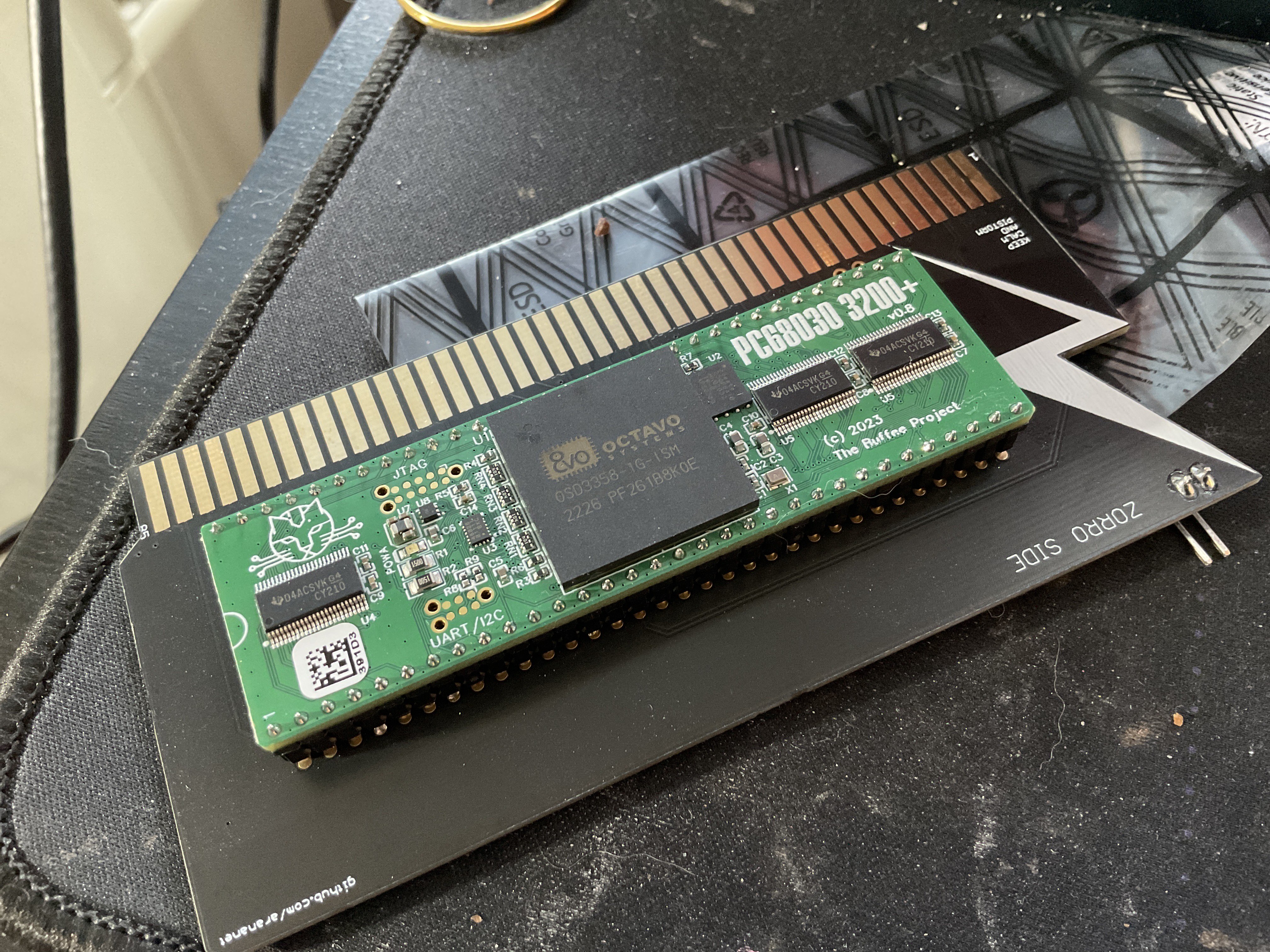
<img src="https://raw.githubusercontent.com/lostcatproductions/lostcatproductions.github.io/master/images/slotted_Buffee.jpg" alt="" /></p>

<p>Yes, the irony that these are "PiStorm" CPU boards is not lost on me. Sigh…</p>

<p>And completely unrelated, I also got my 49" 4K monitor back for Lego-brick sized gaming. Combined with the Amiga to Component adapters it makes for some gorgeous graphics even if lowres is a little absurd on such a screen.</p>

<h2 id="greenpak-rework">GreenPAK Rework</h2>
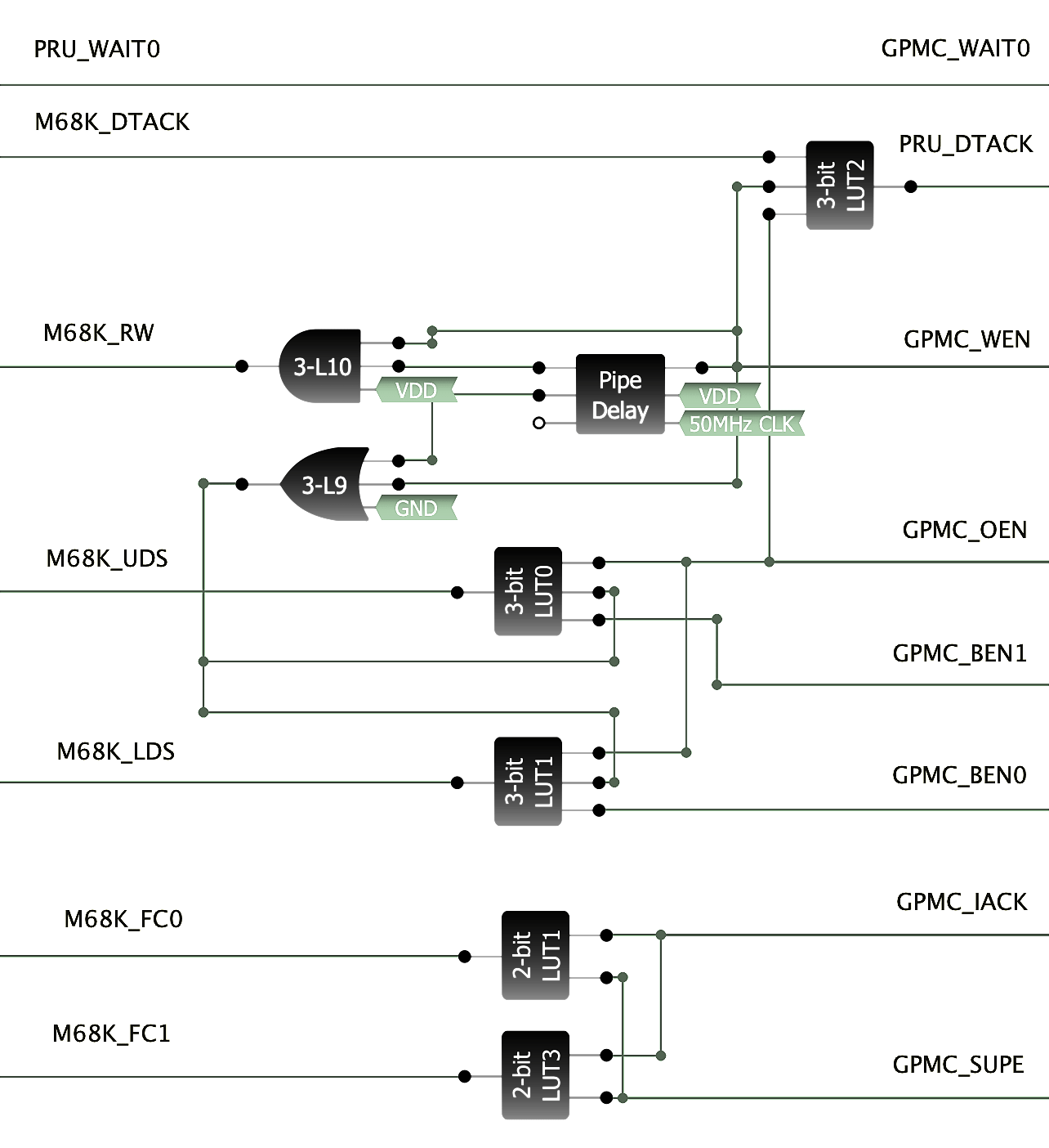
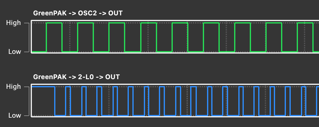
<p>So I've completely reworked the GreenPAK to essentially eliminate most of what it was doing. It still massages thw R/W, xDS and FCx pins, mostly because the ABSOLUTELY HORRENDOUS LATENCY can be compensated for. But the wait behaviour is completely gone – you can see we're doing nothing but feeding the signal more-or-less RAW to the MCU and back again. More importantly, the MCU itself is now controlling it's own memory controller.</p>

<p><img src="https://raw.githubusercontent.com/lostcatproductions/lostcatproductions.github.io/master/images/nuGreenPAK.png" alt="" /></p>

<p>What we're doing is offloading the STUPIDLY SLOW GreenPAK behaviour to the only somewhat slow PRU. This is a RISC coprocessor built into the TI MCUs which is highly deterministic. It nominally works at 200MHz which means we have a 5ns cycle time compared to the 15-20ns delay on the GreenPAK – per function! I've had the PRU clocked up to 333MHz just fine which is a 3ns cycle time – that's a full order of magnitude faster than the GreenPAK. An FPGA it is not, but it's a big improvement.</p>

<p>Okay, maybe some ASCII Art will help here.</p>
<div class="language-plaintext highlighter-rouge"><div class="highlight"><pre class="highlight"><code>         AM335x                                 68K BUS
    --------------------.
    pr1_pru0_pru_r3x_4  | &lt;--------------------  CLK7    
    pr1_pru0_pru_r3x_7  | --------------------&gt;  ECLK    
    pr1_pru0_pru_r3x_16 | &lt;--------------------  VPA     
    pr1_pru0_pru_r3x_0  | --------------------&gt;  VMA     
                        |     .-----------.    
                  WAIT0 | &lt;-- |12       7 | &lt;--  DTACK  
       (GPIO_IACK) CSN2 | --&gt; |20       3 | --&gt;  UDS    
                    WEN | --&gt; |18 Green 4 | --&gt;  LDS    
                    OEN | --&gt; |19  PAK  5 | --&gt;  FC0     
                   BEN0 | --&gt; |16       10| --&gt;  FC1     
                   BEN1 | --&gt; |17       6 | --&gt;  R/W     
        (GPIO_SUPE) A24 | --&gt; |13         |
                        |     |           | 1, 14 Vcc      
    pr1_pru0_pru_r3x_6  | --- | 2         | 8, 9  I2C          
    pr1_pru0_pru_r3x_12 | --- |15         | 11    Ground
    --------------------'     '-----------'
</code></pre></div></div>

<p>First the DTACK. We do use one gate to basically merge the bus DTACK, as well as the WEN and OEN signals we're emitting from the GPMC memory controller. The logic is rather simple to avoid any more delays than we ABSOLUTELY need to. In this case what we want is for our PRU_DTACK signal to rise when we're in S7 (to synchronize with the bus clock) and fall when the bus is ready (normal DTACK use). The OEN and WEN signals will be used here to signify the S7 state as we can precisely control their timing.</p>

<p>This does put a LOT of extra load on the PRU which originally was just going to be an E-Clock creator. Now in addition to this we need to track CPU states (which are on either edge – so happen twice as fast) and watch for wait states. It's a lot, but I'm making progress. I've ran some tests and I'm back to the point of being able to read ROM fine, so it's only DRAM now.</p>

<p>You might wonder why? Well, simple because the GreenPAK does not have the bus clock while the PRU does. The fact that it might be faster is a bonus, but really, it's about the clock. When we hit our 98% read/write accuracy, the 2% failure was because we'd fall out of phase with the bus clock and perform a read or write while the bus latches were still engaged.</p>

<p>In a nut-shell, our "approximate" clock is not good enough. We must be synchronized to the Amiga's bus clock, perfectly. I don't know if this is an Amiga-ism as the 68000 is "supposed to be" asynchronous, but if it can be made to work there, it will work anywhere.</p>

<h1 id="firmware-update">Firmware Update</h1>

<p>I won't hide that PJIT and Apple's DR share a LOT in common. I didn't actually know this at the time though, so it was "clean room". However, knowing this now has helped give me some insight on some critical optimization strategies. We can actually look at the Apple source code for the emulator to see the improvement.</p>

<h2 id="apple-68lc040-emulator">Apple 68LC040 "Emulator"</h2>
<div class="language-plaintext highlighter-rouge"><div class="highlight"><pre class="highlight"><code>    Interpretive Dispatch Table
        lis     data, 0x0004
        b       add_w_shifted_data_d2
    
    Interpretive Semantic Routines
    add_w_shifted_data_d2:
        rlwimi  disp_table, prefetch_data, 3, 13, 28
        rlwinm  immed_data, d2, 16, 0, 15
        mtlr    disp_table
        addco.  data, data, immed_data
        lhau    prefetch_data, 2(pc)
        mfxer   ccr_x
        rlwimi  d2, data, 16, 16, 31
        bgelr+  cr2
        b       process_special_event

    Interpretive Code Path: 10~12 cycles (normally)
</code></pre></div></div>

<p>The Interpretive Dispatch Table was 512KB of basically every 68000 opcode – all 65536 – even the thousands of illegal opcodes – arranged in a pattern of non-jump and jump instructions. The non-jump was a prefix instruction which would attempt to mitigate as much as possible any uniqueness from the common subroutine. Sometimes this was impossible, and a lot of decode work was still done in the common routine – in other cases, the whole 68000 instruction could be emulated in one opcode.</p>

<p>However, these instructions weren't "inline" so a branch was still necessary. In these cases, the IDT would jump to a short sequence which would simply load the opcode and then jump again. This was far from efficient, and Eric Traut solved this with the cache.</p>

<p>The Apple Dynamic Recompiler (DR) improved the emulator quite a bit – in some cases, doubling its speed, and did so without significantly breaking how the former worked, allowing the ROM to switch between emulation and DR mode as necessary.</p>

<h2 id="apple-68lc040-dynamic-recompiler">Apple 68LC040 "Dynamic Recompiler"</h2>
<div class="language-plaintext highlighter-rouge"><div class="highlight"><pre class="highlight"><code>    DR Cache
        lis     data, 0x0004
        bl      dr_add_w_shifted_data_d2
        lhau    prefetch_data, 2(pc)
        bt      cr_sp_event, handle_special_event 
                        
    DR Semantic Routines
    dr_add_w_shifted_data_d2:
        siwi    immed_data, d2, 16
        addco.  data, data, immed_data
        riwimi  d2,data, 16,16,31
        mixer   ccr_x
        bir

    Dynamically Recompiled Code Path: 6 cycles (normally)
</code></pre></div></div>

<p>The cache is now organized much like a conventional CPU cache consisting of cache lines – each cache line was comprised of 32 cache line entries with each entry being four PowerPC opcodes. This means a whole CLE is 16 bytes and the whole CL is 512 bytes. When initialized, the whole line would be translated at once.</p>

<p>Every instruction always took four instructions – the first was copied from the IDT, the second was computed from the DR Offset Table that pointed into the DR Semantic Table (a collection of the opcode stubs), and the third and fourth instructions were simply the exact same for every opcode to perform the 68000 data prefetch. In cases where the instruction is 2- or 3-words, the lhau instruction would load from 4(pc) or 6(pc) respectively.</p>

<p>The last instruction would test for interrupt state and branch to the general event handler routine when necessary. Compared to the frequency of instructions, this was a rare event.</p>

<p>In many cases, 68K opcodes would take one, two or three PowerPC opcodes. In these cases they were labelled as "special case" and instead of caching the branch to the DR Semantic Routine, it called it directly and had that routine write the opcode instead. In the special case of three opcodes, a concession was made to not perform the interrupt-check which could cause some extra interrupt latency – something that was acceptable on the PowerMac, but not so much on other platforms like the Amiga.</p>

<h2 id="buffee-pjit">Buffee PJIT</h2>
<div class="language-plaintext highlighter-rouge"><div class="highlight"><pre class="highlight"><code>    PJIT Cache
        add     r1, r5, offsetof(D2) + 2
        bl      add_w_immediate_4
                            
    PJIT Semantic Routines    
    add_w_immediate_4:
        ldrsh   r0, [r1]
        orrs    r0, r0, #4
        strh    r0, [r1]
        bx      lr

    PJIT Code Path: 3 cycles (normally)
</code></pre></div></div>

<p>There are a few things here that should jump out if you actually tried reading the PowerPC code (and sorry for that, PowerPC assembly is the worst). We're not at all thinking about interrupts, we're not performing any prefetch and we're dealing with D2 as a memory operation.</p>

<h3 id="m68k-interrupt-handling">M68K Interrupt Handling</h3>
<p>The magic here is that we still have and do not disable the interrupt handlers, but instead of doing any actual interrupt handling, all they do is alter the user-mode link register and then return. Now, when the semantic routine is done and the BX LR instruction is encountered, instead of jumping back to the next opcode in the cache, it jumps to the M68K interrupt handler.</p>

<p>This saves us having to do this for every opcode.</p>

<h3 id="m68k-prefetch">M68K Prefetch</h3>
<p>PJIT does not emulate the prefetch (albeit with one exception – the RESET instruction), and of course, with PJIT, instead of handling the extension words and data within the semantic routines, these are prefixed within the PJIT cache itself as reversed order of opcodes, so any PC, address or immediate is already in r1 or r2.</p>

<p>This saves us having to do this for every opcode.</p>

<h3 id="data-registers-in-ram">Data Registers in RAM</h3>
<p>Lastly, because the data registers would overflow our available ARM CPU registers, D2 thru D7 are instead stored in RAM. This may incur latencies depending on where in RAM they're presently stored, but based on its frequency should almost certainly always remain in L1 cache.</p>

<p>However, changing this to D0 does not significantly reduce the number of instructions on either the ARM or PowerPC since neither are capable of working with byte and word values directly. So if this were D0, the sequence would instead be:</p>
<div class="language-plaintext highlighter-rouge"><div class="highlight"><pre class="highlight"><code>    PJIT Cache
        sxth    r0, r3 + Dn
        bl      add_w_immediate_4_D0
                            
    PJIT Semantic Routines    
    add_w_immediate_4_D0:
        orrs    r0, r0, #4
        bfi     r3 + Dn, r0, 0, 16
        bx      lr
        nop
</code></pre></div></div>

<p>Note that we add a nop to the end to round up the length of the routine. The Cortex A8 uses 64-byte (16 instruction) cache lines, so we want to keep these from causing a single opcode from taking up multiple cache lines. This was one of the good lessons from the Apple DR patent – keep your subroutines cache-aligned.</p>

<p>So why not also use four opcodes? Well, it would allow for far more instructions to be inlined, however, even on the Cortex A8, the branch predictor is robust enough that this seldom matters. Also, unlike the PowerPC version, we have a lot of M68K opcodes that only take one or two instructions meaning that we'd be adding a whole lot of NOPs and there's just nothing to do in those spare slots.</p>

<p>So what about the flip side? Well, just one opcode means we're just always doing a branch. There are plenty of M68K opcodes that can be done in one ARM instruction (including most branches), and it would mean we're never adding NOPs to the cache (except for the NOP instruction), but for all the rest, it does mean always jumping to a specific subroutine handler. This makes the semantic routines rather large – about 2MB or four times the size that PJIT is with it's 512KB opcode table + semantic routines.</p>

<p>One of the other interesting things from the Apple Patents though is the low-energy required to assemble the DR Cache opcodes. It really is elegant having the DR Offset Table and DR Semantic Routines. This means the IDT can still be used directly for interpreter use. However, since we handle extension words quite differently, this had to be adapted somewhat. But the benefit is huge.</p>

<h3 id="new-pjit-structure">New PJIT Structure</h3>

<p>PJIT (PJIT Instruction Table) holds the single prefix instruction for every opcode. This table is exactly 256KB and should be aligned to 256KB in memory.</p>

<p>PJSR (PJIT Semantic Routines) holds all the opcode subroutines needed to complete the M68K instruction after executing the prefix operation. This should not require more than 64KB of RAM. The PSR exists and remains entirely in the bootloader SRAM.</p>

<p>PJOT (PJIT Offset Table) holds a 16-bit offset into the PSR with the low two bits indicating the type of routine in the PSR. This should take exactly 128KB of RAM (2x64K).</p>

<p>I'm still ironing out the details and changes to the code, but this is going to make the tables a LOT smaller and this means much more liklihood that they're in cache – this isn't that much larger than the sum of the L2 and L1 caches on our Cortex A8, and that's fantastic.</p>

<h2 id="on-a-personal-note">On A Personal Note</h2>

<p>I am very sorry for all the delays. I don't want to get into the details but let's say that getting old sucks. I'm getting better though and I've started to feel a little bit more energetic and getting back into things.</p>

<p>Let's hope 2024 is a better year.</p>

<p>And for anyone still out there reading this, thank you for your patience.</p>]]></content><author><name>Renee Cousins</name></author><summary type="html"><![CDATA[When Apple introduced PowerPC they also introduced the idea of system-level emulation providing a stop-gap for applications (and ROM) to remain as 68K code for a while. The emulator, written originally by Gary Davidian, introduced some novel features, but wasn't terribly fast – it was a later version made by Eric Traut that introduced us to the term "Dynamic Recompiler" which would become the forerunner of Just-In-Time (JIT) Compilers. It serves as one of only two emulators which use this model.]]></summary></entry><entry><title type="html">GreenPAK Abuse 101</title><link href="http://www.buffee.ca/greenpak-abuse/" rel="alternate" type="text/html" title="GreenPAK Abuse 101" /><published>2023-05-04T00:00:00+00:00</published><updated>2023-05-04T00:00:00+00:00</updated><id>http://www.buffee.ca/greenpak-abuse</id><content type="html" xml:base="http://www.buffee.ca/greenpak-abuse/"><![CDATA[<p>When we originally chose to use the AM3358, one of the major reasons for it was the existence of the GPMC or General Purpose Memory Controller. We incorrectly assumed it would be able to cope with virtually any kind of bus, including the 68000, so we eventually had to add a small CPLD to our board – the GreenPAK. But it wasn't without its own issues.</p>

<p>Aside from the abysmal number of pins, the snafu regarding the pin numbering reversing between packages and the very difficult to use visual editor (please give us Verilog Renesas!), the big problem we've had with the GreenPAK is it's speed – it is not a terribly fast chip. While a Xilinx CPLD might have a 5ns pin-to-pin minimum, the GreenPAK has 12ns simply passing through a logic cell and about 20ns simply getting through the GPIO structure!</p>

<p>Shockingly, we're able to deal with most of that, but one thing that we couldn't was the amount of jitter the meagre 25MHz clock created. At this speed a simple flip flop takes 40ns with about a +/-20ns margin of error. This is well outside of the timing requirements for the 68000 and made adjusting the GPMC signals to conform to 68000's almost impossible.</p>

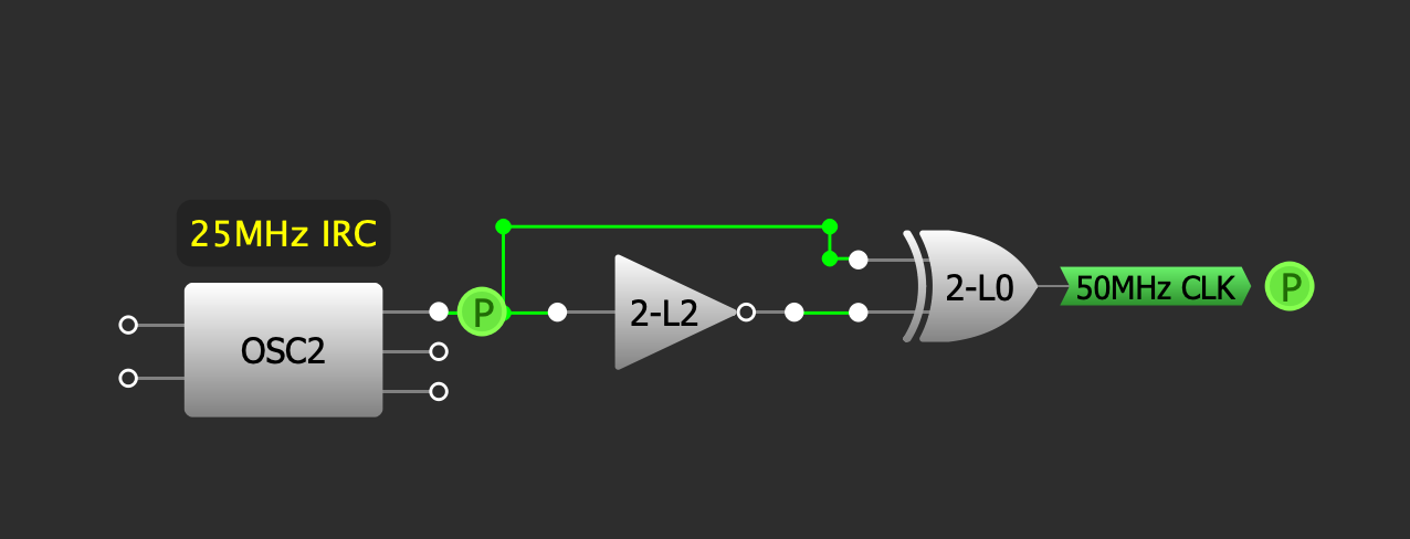
<p>So we overclocked it.</p>

<p><img src="https://raw.githubusercontent.com/lostcatproductions/lostcatproductions.github.io/master/images/clock_coubler.PNG" alt="" /></p>

<p>Using an old trick from Commodore, we used a delay and an XOR gate to create a 50MHz clock, and guess what? It works.</p>

<p><img src="https://raw.githubusercontent.com/lostcatproductions/lostcatproductions.github.io/master/images/clock_doubled.PNG" alt="" /></p>

<p>Is this a perfect solution? Well, no, but it does improve the precision of any timing by a factor of two and that's allowed us to hit a record-high of 99.8% bus accuracy! That's unfortunately a long way from 100% which is where we need to be, but wow, we're close.</p>

<p>One of the last remaining hickups was tied to how we're using signals from the GPMC for 68K bus signals, notably we use the Write Enable (WE) signal for both the Read Write (RW) signal and the Upper and Lower Data Strobe (UDS/LDS). This was problematic as we ended up needing to have realtively fixed timing for both these and that wasn't working. We have a new version of the GreenPAK code which now decouples these two allowing us to change both the delay from the WE to the xDS signal start and the extra time for the RW signal at the end. coupled with our new found precision, I'm confident we'll have our timing 100% soon enough.</p>

<p>If we're very lucky, a v0.4 release very soon!</p>

<p>Until then, happy hacking everyone, and May the 4th be with you!</p>]]></content><author><name>Renee Cousins</name></author><summary type="html"><![CDATA[When we originally chose to use the AM3358, one of the major reasons for it was the existence of the GPMC or General Purpose Memory Controller. We incorrectly assumed it would be able to cope with virtually any kind of bus, including the 68000, so we eventually had to add a small CPLD to our board – the GreenPAK. But it wasn't without its own issues.]]></summary></entry><entry><title type="html">Buffee Firmware Beta v0.3</title><link href="http://www.buffee.ca/buffee-beta-release/" rel="alternate" type="text/html" title="Buffee Firmware Beta v0.3" /><published>2023-04-18T00:00:00+00:00</published><updated>2023-04-18T00:00:00+00:00</updated><id>http://www.buffee.ca/buffee-beta-release</id><content type="html" xml:base="http://www.buffee.ca/buffee-beta-release/"><![CDATA[<p>Progress on "PJIT 2.0" has gone well so far and we're now into our third beta release. Executing code is still problematic when the bus timing is still not 100%, but we're getting there. Users are welcome to download the binary and play around, we'd be absolutely thrilled if anyone could play around with the GPMC settings and let us know what works and what doesn't.</p>

<h1 id="programming">Programming</h1>

<p>You're welcome to program this either with a 3.3V UART or JTAG connection using either the <a href="https://github.com/nonarkitten/pseudo-jit/releases/download/v0.3/pjit.bin">binary here</a> or the <a href="https://github.com/nonarkitten/pseudo-jit/releases/download/v0.3/pjit.elf">ELF file here</a> respectively. When using UART, set your terminal program to 115,200 baud and 8N1 parity. When you first connect, you should see a steady stream of 'C' characters at which point you can XMODEM transfer the binary into RAM. It should start immediately.</p>

<h2 id="flashing-the-firmware">Flashing the Firmware</h2>

<p>Among the various options is to program the firmware to SPI Flash. I don't recommend doing this yet.</p>

<h2 id="recovering-the-flash">Recovering the Flash</h2>

<p>If you didn't listen and anything bad happens, you should be able to recover by rebooting the system while holding the Escape key in the terminal window. You should see a message saying that flash has been erased and you'll be back to the repeating 'C'.</p>

<h1 id="firmware">Firmware</h1>

<p>Upon boot, you should see the PJIT banner as well as some boot up noise. The firmware includes both the bootloader and the 68K emulator so there is no second-stage required.</p>
<div class="language-plaintext highlighter-rouge"><div class="highlight"><pre class="highlight"><code>              ____ ______________
  ______     |    |   \__    ___/
  \  __ \    |    |   | |    |
  |  |_) )\__|    |   | |    |
  |   __/\________|___| |____|
  |__|

[BOOT] Build Version, v0.3, Date Apr 18 2023, Time 14:00:26
[I2C0] Scanning bus..
[I2C0] EEPROM Detected ($50)
[I2C0] Settings loaded, last boot was good
[I2C0] GreenPAK Detected ($08~$0B) 
[I2C0] GreenPAK Protection Bits: $00 $00 $00
[I2C0] GreenPAK good
[I2C0] PMIC ID: TPS65217C
[I2C0] PMIC DCDC voltage: 1.35
[I2C0] Nitro mode enabled
[CLK7] Main bus clock measured at 7.158
[GPMC] Trimming Core PLL to: 966
[GPMC] SYNC VIOLATION: t-&gt;CSOFFTIME &gt;= (t-&gt;ACCESSTIME+1)
[BOOT] Initializing cache
[BOOT] Initializing opcode tables
[BOOT] Image 402F0400 ~ 40302560 (74080 bytes)
[BOOT] Stack 403081E5 ~ 4030FFF8 (32275 bytes)
[I2C0] Saving and verifying settings (CRC=823A)
[BOOT] Completed in 0.19795 seconds

MENU
----
TESTS:
 1. Quick-test DDR memory
 2. Dump first 4K of SPI Flash
 3. Quick-test SPI flash
 4. Test GPMC
 5. Test printf
 6. Run Native BogoMIPS test
 7. Run PJIT BogoMIPS test
SETUP:
 J. Jump to PJIT
 C. Set E Clock Divider
 R. Run MCL68K
 S. Manage SPI Flash
 E. Manage EEPROM Config
 G. Manage GreenPAK
 H. Print help (this)
 X. Reboot
Ready
] █
</code></pre></div></div>

<p>At the moment, we're using the MCL68k emulator due to it's rather terse size, but this is only an interim fix while we determine the best settings for the bus timing. So the 'J' option will not work.</p>

<h2 id="configuration">Configuration</h2>

<p>The user can now set up the EEPROM settings used to configure Buffee at boot. These will also be alterable on the fly – this is only setting the state of the CPU during boot. You can get there by entering 'E' and then '3' to display and change EEPROM settings. The default options look like this:</p>
<div class="language-plaintext highlighter-rouge"><div class="highlight"><pre class="highlight"><code>] 3
Config:
A.  CPU: 
B.  Clock: 7.158 MHz
C.  I$: Enabled
D.  I$ Mask: 0000
E.  D$: Enabled
F.  D$ Mask: 0000
G.  MAPROM Enabled
    000000~07FFFF
    POST:
H.    Long Mem Test Disabled
I.    GreenPAK Test Enabled
J.    Bus Clock Test Enabled
K.    Automap Enabled
L.  MCU CLK: 1000
M.  PMIC Voltage: 1.35
    PJIT Cache:
N.    Block Size: 16384 bytes
O.    Block Count: 1
      Cache Size: 16 kB
X.  Return to previous menu
</code></pre></div></div>
<p>We'll also be adding in options to overclock the 6800 bus which pushes the CIAs to a 9-cycle period instead of 10. We did try other values, but at 8-cycles, they would only respond to every-other-access and were thus quite a bit slower. Still, a 10% speed up on the slowest part of most 68000 machines isn't bad.</p>

<p>You can save these, reset to defaults, and when you reboot, they should be automatically applied. I would strongly not recommend trying to overclock Buffee <strong><em>AND</em></strong> run from Flash incase your settings brick Buffee. They shouldn't, but <em>caveat emptor</em>.</p>

<h2 id="gpmc-timing">GPMC Timing</h2>

<p>The most important option right now is 4. Test GPMC, which provides you with a sub menu.</p>
<div class="language-plaintext highlighter-rouge"><div class="highlight"><pre class="highlight"><code>1. Endian test
2. Dump first 16 words of ROM
3. ROM speed test
4. CIA speed test
5. Agnus read/write
6. CIA read/write
7. Chip RAM read/write
A. Perform all tests and exit
D. Set GPMC timing to default
T. Set GPMC timing
X. Exit to main menu
] █
</code></pre></div></div>

<p>Running all the tests should show something like this when it's working:</p>
<div class="language-plaintext highlighter-rouge"><div class="highlight"><pre class="highlight"><code>[GPMC] Endian Check: exec 34.2 (28 Oct 1987)
[GPMC] Bytes NOT swapped
[GPMC] Read words (LE:BE)
[GMPC] $00000000: 1111:1111  f94e:4ef9  fc00:00fc  d200:00d2 
[GMPC] $00000008: 0000:0000  ffff:ffff  2200:0022  0500:0005 
[GMPC] $00000010: 2200:0022  0200:0002  ffff:ffff  ffff:ffff 
[GMPC] $00000018: 7865:6578  6365:6563  3320:2033  2e34:342e 
[GPMC] Test passed and matches
[GPMC] Performing benchmark with ROM
[GPMC] Read 1048576 words in 0.78 s, expecting 0.559s
[GPMC] Read ROM at 2.55 MB/s, expecting 3.58MB/s
[GPMC] Test passed
[GPMC] Performing benchmark with CIA
[GPMC] Read 262144 words in 0.36 s, expecting 0.358 s
[GPMC] Read CIA at 699.10 kB/s, expecting 716kB/s
[GPMC] Test passed
[GPMC] DeniseID: 0xFFFF (OCS)
[GPMC] JOYxDAT Check: 0xa2a3 0xa2a3 (6 avg bit errors)
[GPMC] Test passed
[GPMC] JOYxDAT Check: 0x5253 0x5050 (5 avg bit errors)
[GPMC] Test passed
[GPMC] CIAA Read ok (03 == 03)
[GPMC] CIAA Read ok (00 == 00)
[GPMC] CIAA Timer test (should be 180 ticks)
[GPMC] CIAA timer A Start: 0x00000000
[GPMC] CIAA timer A End: 0x000000b4
[GPMC] CIAA timer A Elapsed: 0
[GPMC] Test passed
[GPMC] Performing RAM test
[GMPC] $00020000: 0000  0101  0202  0303  0404  0505  0606  0707 
[GMPC] $00020008: 0808  0909  0a0a  0b0b  0c0c  0d0d  0e0e  0f0f 
[GMPC] $00020010: 1010  1111  1212  1313  1414  1515  1616  1717 
[GMPC] $00020018: 1818  1919  1a1a  1b1b  1c1c  1d1d  1e1e  1f1f 
[GMPC] $00020020: 2020  2121  2222  2323  2424  2525  2626  2727 
[GMPC] $00020028: 2828  2929  2a2a  2b2b  2c2c  2d2d  2e2e  2f2f 
[GMPC] $00020030: 3030  3131  3232  3333  3434  3535  3636  3737 
[GMPC] $00020038: 3838  3939  3a3a  3b3b  3c3c  3d3d  3e3e  3f3f 
[GMPC] $00020040: 4040  4141  4242  4343  4444  4545  4646  4747 
[GMPC] $00020048: 4848  4949  4a4a  4b4b  4c4c  4d4d  4e4e  4f4f 
[GMPC] $00020050: 5050  5151  5252  5353  5454  5555  5656  5757 
[GMPC] $00020058: 5858  5959  5a5a  5b5b  5c5c  5d5d  5e5e  5f5f 
[GMPC] $00020060: 6060  6161  6262  6363  6464  6565  6666  6767 
[GMPC] $00020068: 6868  6969  6a6a  6b6b  6c6c  6d6d  6e6e  6f6f 
[GMPC] $00020070: 7070  7171  7272  7373  7474  7575  7676  7777 
[GMPC] $00020078: 7878  7979  7a7a  7b7b  7c7c  7d7d  7e7e  7f7f 
[GMPC] $00020080: 8080  8181  8282  8383  8484  8585  8686  8787 
[GMPC] $00020088: 8888  8989  8a8a  8b8b  8c8c  8d8d  8e8e  8f8f 
[GMPC] $00020090: 9090  9191  9292  9393  9494  9595  9696  9797 
[GMPC] $00020098: 9898  9999  9a9a  9b9b  9c9c  9d9d  9e9e  9f9f 
[GMPC] $000200A0: a0a0  a1a1  a2a2  a3a3  a4a4  a5a5  a6a6  a7a7 
[GMPC] $000200A8: a8a8  a9a9  aaaa  abab  acac  adad  aeae  afaf 
[GMPC] $000200B0: b0b0  b1b1  b2b2  b3b3  b4b4  b5b5  b6b6  b7b7 
[GMPC] $000200B8: b8b8  b9b9  baba  bbbb  bcbc  bdbd  bebe  bfbf 
[GMPC] $000200C0: c0c0  c1c1  c2c2  c3c3  c4c4  c5c5  c6c6  c7c7 
[GPMC] Test passed, 0 errors, 0.0%
[GPMC] 7 of 7 tests passed
</code></pre></div></div>

<p>Right now, most commonly, either the RAM or CIA tests fail. This is due to a timing issue we haven't quite corrected yet. We can now use the 'T' option to change the GPMC timing on the fly, to try and dial in a better setting. Right now, the sync behaviour with DTACK and S4 state is controlled by the GreenPAK and isn't adjustable. We may have to change that if we're not able to find good settings.</p>

<p>When changing the timing, we'll be preseted with a timing diagram, the actualy numeric values and then a prompt to change every one. You can simply press enter to accept the default value in brackets. When you are done, it will draw you another cute timing diagram and you can then run more tests.</p>

<div class="language-plaintext highlighter-rouge"><div class="highlight"><pre class="highlight"><code>] t
Timing Diagram:
          11111111112222222
012345678901234567890123456
                         *     Access
___                       _
   |_____________________|     AS
        *                      S4 Sync
                           
|_________________________|    DS (Read)
_____                      
     |____________________|    DS (Write)

[GPMC] Cycle Time: 27
[GPMC] Access Time: 25
[GPMC] nCS Timing (ON/OFF): 3/25
[GPMC] nRE Timing (ON/OFF): 0/26
[GPMC] nWE Timing (ON/OFF): 5/26
Set Cycle Time     (0-31) [27]: 
Set Access Time    (0-31) [25]: 21
Set AS On-Time     (0-15) [ 3]: 
Set AS Off-Time    (0-31) [25]: 
Set Read On-Time   (0-15) [ 0]: 
Set Read Off-Time  (0-31) [26]: 
Set Write On-Time  (0-15) [ 5]: 7
Set Write Off-Time (0-31) [26]: 
Timing Diagram:
          11111111112222222
012345678901234567890123456
                     *         Access
___                       _
   |_____________________|     AS
        *                      S4 Sync
                           
|_________________________|    DS (Read)
_______                    
       |__________________|    DS (Write)
       
</code></pre></div></div>

<h1 id="we-need-you">We Need You!</h1>

<p>This is where the testing part comes in. We need to find more reliable timing parameters – 99% just doesn't cut it. We're working hard on this, but we're welcome to any Beta Buffee owners out there playing around and seeing what works for them. Is NTSC or PAL more forgiving? What about the 1000 versus 500? All great questions!</p>

<p>Anyway, this is a pretty long post already and I think I'll stop here. Next post we're going to be talking about how to run ARM code directly from 68000 code for when 1000 MIPS isn't enough.</p>

<p>TTFN</p>]]></content><author><name>Renee Cousins</name></author><summary type="html"><![CDATA[Progress on "PJIT 2.0" has gone well so far and we're now into our third beta release. Executing code is still problematic when the bus timing is still not 100%, but we're getting there. Users are welcome to download the binary and play around, we'd be absolutely thrilled if anyone could play around with the GPMC settings and let us know what works and what doesn't.]]></summary></entry><entry><title type="html">Welcome to the new site!</title><link href="http://www.buffee.ca/new-site/" rel="alternate" type="text/html" title="Welcome to the new site!" /><published>2023-04-18T00:00:00+00:00</published><updated>2023-04-18T00:00:00+00:00</updated><id>http://www.buffee.ca/new-site</id><content type="html" xml:base="http://www.buffee.ca/new-site/"><![CDATA[<p>We've updated our website to include commenting, provide RSS feeds as well as make it easier to find old aticles. There are still some bugs to iron out (like the splash screen never coming back), but I wanted to get this out sooner rather than later. This is a short one today, hope everyone's enjoying spring.</p>]]></content><author><name>Renee Cousins</name></author><summary type="html"><![CDATA[We've updated our website to include commenting, provide RSS feeds as well as make it easier to find old aticles. There are still some bugs to iron out (like the splash screen never coming back), but I wanted to get this out sooner rather than later. This is a short one today, hope everyone's enjoying spring.]]></summary></entry><entry><title type="html">What the GCC?</title><link href="http://www.buffee.ca/what-the-gcc/" rel="alternate" type="text/html" title="What the GCC?" /><published>2023-01-09T00:00:00+00:00</published><updated>2023-01-09T00:00:00+00:00</updated><id>http://www.buffee.ca/what-the-gcc</id><content type="html" xml:base="http://www.buffee.ca/what-the-gcc/"><![CDATA[<p>Happy New Year! With a new year comes new revelations and wow do I have a doozy – ARM GCC is just completely broken. I'm not saying it doesn't produce working code but there are cases where it produces obscenely poor performing code.</p>

<p>So the following is a pedagogical example of a direct-threaded interpreter.</p>
<div class="language-c highlighter-rouge"><div class="highlight"><pre class="highlight"><code><span class="cp">#define NEXT goto **ip++
</span>
<span class="kt">int</span> <span class="nf">main</span><span class="p">(</span><span class="kt">void</span><span class="p">)</span> <span class="p">{</span>
  <span class="k">static</span> <span class="kt">void</span>  <span class="o">*</span><span class="n">prog</span><span class="p">[]</span> <span class="o">=</span> <span class="p">{</span>
    <span class="o">&amp;&amp;</span><span class="n">next1</span><span class="p">,</span><span class="o">&amp;&amp;</span><span class="n">next2</span><span class="p">,</span>
    <span class="o">&amp;&amp;</span><span class="n">next1</span><span class="p">,</span><span class="o">&amp;&amp;</span><span class="n">next3</span><span class="p">,</span>
    <span class="o">&amp;&amp;</span><span class="n">next1</span><span class="p">,</span><span class="o">&amp;&amp;</span><span class="n">next4</span><span class="p">,</span>
    <span class="o">&amp;&amp;</span><span class="n">next1</span><span class="p">,</span><span class="o">&amp;&amp;</span><span class="n">next5</span><span class="p">,</span>
    <span class="o">&amp;&amp;</span><span class="n">next1</span><span class="p">,</span><span class="o">&amp;&amp;</span><span class="n">loop</span>
  <span class="p">};</span>
  <span class="kt">void</span> <span class="o">**</span><span class="n">ip</span><span class="o">=</span><span class="n">prog</span><span class="p">;</span>
  <span class="kt">int</span>    <span class="n">count</span> <span class="o">=</span> <span class="mi">100000000</span><span class="p">;</span>
  <span class="n">NEXT</span><span class="p">;</span>
 <span class="nl">next1:</span> <span class="n">NEXT</span><span class="p">;</span>
 <span class="nl">next2:</span> <span class="n">NEXT</span><span class="p">;</span>
 <span class="nl">next3:</span> <span class="n">NEXT</span><span class="p">;</span>
 <span class="nl">next4:</span> <span class="n">NEXT</span><span class="p">;</span>
 <span class="nl">next5:</span> <span class="n">NEXT</span><span class="p">;</span>
 <span class="nl">loop:</span>
  <span class="k">if</span> <span class="p">(</span><span class="n">count</span><span class="o">&gt;</span><span class="mi">0</span><span class="p">)</span> <span class="p">{</span>
    <span class="n">count</span><span class="o">--</span><span class="p">;</span>
    <span class="n">ip</span><span class="o">=</span><span class="n">prog</span><span class="p">;</span>
    <span class="n">NEXT</span><span class="p">;</span>
  <span class="p">}</span>
  <span class="n">exit</span><span class="p">(</span><span class="mi">0</span><span class="p">);</span>
<span class="p">}</span>
</code></pre></div></div>
<p>When compiled with -Os, this produces abysmal code. What you're seeing here is the code for each next# statement which is MOSTLY the NEXT statement. This is loading the address to jump to into register R2, branching to .L2 which then copies R2 into the program counter PC. Okay.</p>
<div class="language-armasm highlighter-rouge"><div class="highlight"><pre class="highlight"><code><span class="err">.</span><span class="nl">L2</span>
        <span class="nb">mov</span>     <span class="nv">pc</span><span class="o">,</span> <span class="nv">r2</span>    <span class="no">@</span> <span class="nv">indirect</span> <span class="nv">register</span> <span class="nv">jump</span>
<span class="err">.</span><span class="nl">Lnext1</span><span class="err">:</span>
        <span class="nb">ldr</span>     <span class="nv">r2</span><span class="o">,</span> <span class="o">[</span><span class="nv">r3</span><span class="o">],</span> <span class="o">#</span><span class="mi">4</span>
        <span class="nb">b</span>       <span class="mf">.</span><span class="nv">L2</span>
<span class="err">.</span><span class="nl">Lnext2</span><span class="err">:</span>
        <span class="nb">ldr</span>     <span class="nv">r2</span><span class="o">,</span> <span class="o">[</span><span class="nv">r3</span><span class="o">],</span> <span class="o">#</span><span class="mi">4</span>
        <span class="nb">b</span>       <span class="mf">.</span><span class="nv">L2</span>
        <span class="err">...</span>
</code></pre></div></div>
<p>Well, if we compile it with -O3 which should produce faster code and shouldn't produce smaller code, we instead see this:</p>
<div class="language-armasm highlighter-rouge"><div class="highlight"><pre class="highlight"><code><span class="err">.</span><span class="nl">Lnext1</span><span class="err">:</span>
        <span class="nb">ldr</span>     <span class="nv">r2</span><span class="o">,</span> <span class="o">[</span><span class="nv">r3</span><span class="o">],</span> <span class="o">#</span><span class="mi">4</span>
        <span class="nb">mov</span>     <span class="nv">pc</span><span class="o">,</span> <span class="nv">r2</span>    <span class="no">@</span> <span class="nv">indirect</span> <span class="nv">register</span> <span class="nv">jump</span>
<span class="err">.</span><span class="nl">Lnext2</span><span class="err">:</span>
        <span class="nb">ldr</span>     <span class="nv">r2</span><span class="o">,</span> <span class="o">[</span><span class="nv">r3</span><span class="o">],</span> <span class="o">#</span><span class="mi">4</span>
        <span class="nb">mov</span>     <span class="nv">pc</span><span class="o">,</span> <span class="nv">r2</span>    <span class="no">@</span> <span class="nv">indirect</span> <span class="nv">register</span> <span class="nv">jump</span>
        <span class="err">...</span>
</code></pre></div></div>
<p>See that? We lost a completely useless branch and the code is smaller. But we're not done. While there is NO compiler option that will improve this further, this is what we SHOULD see with either -Os or -O3:</p>
<div class="language-armasm highlighter-rouge"><div class="highlight"><pre class="highlight"><code><span class="err">.</span><span class="nl">Lnext1</span><span class="err">:</span>
        <span class="nb">ldr</span>     <span class="nv">pc</span><span class="o">,</span> <span class="o">[</span><span class="nv">r3</span><span class="o">],</span> <span class="o">#</span><span class="mi">4</span>   <span class="no">@</span> <span class="nv">indirect</span> <span class="nv">register</span> <span class="nv">jump</span>
<span class="err">.</span><span class="nl">Lnext2</span><span class="err">:</span>
        <span class="nb">ldr</span>     <span class="nv">pc</span><span class="o">,</span> <span class="o">[</span><span class="nv">r3</span><span class="o">],</span> <span class="o">#</span><span class="mi">4</span>   <span class="no">@</span> <span class="nv">indirect</span> <span class="nv">register</span> <span class="nv">jump</span>
        <span class="err">...</span>
</code></pre></div></div>
<p>That's one instruction per NEXT. Ouch. Not only is this now one instruction instead of three, not only would this save unnecessary abuse on the branch predictor, but we also have avoided using a temporarty register: R2. GCC likes to make code-stubs in -Os even when said stubs are only one instruction and this is very bad, but the other problem is that GCC also doesn't understand that on ARM, the program counter is a general purpose register, and with few exceptions can be treated like any other and that means using LDR directly into PC.</p>

<p>Of course the fix here would be to define NEXT with assembly. But this isn't portable anymore and guess what – it doesn't even work because GCC doesn't see this as a "jump" and will optimize out all the computed goto labels. To date, I've not found a reasonable workaround, portable or not.</p>
<div class="language-c highlighter-rouge"><div class="highlight"><pre class="highlight"><code><span class="cp">#define NEXT asm __volatile("ldr\tpc, [%0], #4" : "+r"(ip))
</span></code></pre></div></div>

<p>It's with some bit of irony though, that as much as GCC sometimes likes to pointlessly create these little vestigial code stubs, there's also times when it will create a lot of EXCESS code, even with -Os. Here's PJIT's cache routine.</p>
<div class="language-c highlighter-rouge"><div class="highlight"><pre class="highlight"><code><span class="kt">uint32_t</span><span class="o">*</span> <span class="nf">cache_find_entry</span><span class="p">(</span><span class="kt">uint32_t</span> <span class="n">m68k_addr</span><span class="p">)</span> <span class="p">{</span>
    <span class="kt">uint32_t</span> <span class="n">tag</span> <span class="o">=</span> <span class="p">((</span><span class="n">m68k_addr</span> <span class="o">&gt;&gt;</span> <span class="mi">1</span><span class="p">)</span> <span class="o">&gt;&gt;</span> <span class="p">(</span><span class="n">BLOCKLEN</span> <span class="o">+</span> <span class="n">INDEXLEN</span><span class="p">));</span>
    <span class="kt">uint32_t</span> <span class="n">idx</span> <span class="o">=</span> <span class="p">((</span><span class="n">m68k_addr</span> <span class="o">&gt;&gt;</span> <span class="mi">1</span><span class="p">)</span> <span class="o">&gt;&gt;</span> <span class="n">BLOCKLEN</span><span class="p">)</span> <span class="o">&amp;</span> <span class="p">((</span><span class="mi">1</span> <span class="o">&lt;&lt;</span> <span class="n">INDEXLEN</span><span class="p">)</span> <span class="o">-</span> <span class="mi">1</span><span class="p">);</span>
    <span class="kt">uint32_t</span> <span class="n">off</span> <span class="o">=</span> <span class="p">((</span><span class="n">m68k_addr</span> <span class="o">&gt;&gt;</span> <span class="mi">1</span><span class="p">)</span> <span class="o">&amp;</span> <span class="p">((</span><span class="mi">1</span> <span class="o">&lt;&lt;</span> <span class="n">BLOCKLEN</span><span class="p">)</span> <span class="o">-</span> <span class="mi">1</span><span class="p">));</span>

    <span class="k">if</span> <span class="p">((</span><span class="o">*</span><span class="n">cache_tags</span><span class="p">)[</span><span class="n">idx</span><span class="p">]</span> <span class="o">!=</span> <span class="n">tag</span><span class="p">)</span> <span class="p">{</span> <span class="c1">// MISS!</span>
        <span class="n">__cache_clear</span><span class="p">(</span><span class="o">&amp;</span><span class="p">(</span><span class="o">*</span><span class="n">cache_data</span><span class="p">)[</span><span class="n">idx</span><span class="p">][</span><span class="mi">0</span><span class="p">],</span>
          <span class="o">&amp;</span><span class="p">(</span><span class="o">*</span><span class="n">cache_data</span><span class="p">)[</span><span class="n">idx</span><span class="p">][(</span><span class="mi">1</span> <span class="o">&lt;&lt;</span> <span class="n">BLOCKLEN</span><span class="p">)</span> <span class="o">-</span> <span class="mi">2</span><span class="p">]);</span>
        <span class="p">(</span><span class="o">*</span><span class="n">cache_tags</span><span class="p">)[</span><span class="n">idx</span><span class="p">]</span> <span class="o">=</span> <span class="n">tag</span><span class="p">;</span>
    <span class="p">}</span>
    <span class="k">return</span> <span class="o">&amp;</span><span class="p">(</span><span class="o">*</span><span class="n">cache_data</span><span class="p">)[</span><span class="n">idx</span><span class="p">][</span><span class="n">off</span><span class="p">];</span>
<span class="p">}</span>
</code></pre></div></div>
<p>Simple enough, right? Well, GCC in it's infinte wisdom basically rolls that return statement into either code path and assembles them both. That is, the end of the function looks like this:</p>
<div class="language-armasm highlighter-rouge"><div class="highlight"><pre class="highlight"><code>        <span class="err">...</span>
        <span class="nb">add</span>     <span class="nv">ip</span><span class="o">,</span> <span class="nv">ip</span><span class="o">,</span> <span class="nv">r6</span>
        <span class="nb">strh</span>    <span class="nv">r5</span><span class="o">,</span> <span class="o">[</span><span class="nv">ip</span><span class="o">,</span> <span class="o">#-</span><span class="mi">255</span><span class="o">]</span> <span class="no">@</span> <span class="nv">movhi</span>
        <span class="nb">add</span>     <span class="nv">r0</span><span class="o">,</span> <span class="nv">r3</span><span class="o">,</span> <span class="nv">r1</span><span class="o">,</span> <span class="nb">lsl</span> <span class="o">#</span><span class="mi">7</span>
        <span class="nb">lsl</span>     <span class="nv">r0</span><span class="o">,</span> <span class="nv">r0</span><span class="o">,</span> <span class="o">#</span><span class="mi">2</span>
        <span class="nb">add</span>     <span class="nv">r0</span><span class="o">,</span> <span class="nv">r0</span><span class="o">,</span> <span class="o">#-</span><span class="mi">1627389952</span>
        <span class="nb">add</span>     <span class="nv">r0</span><span class="o">,</span> <span class="nv">r0</span><span class="o">,</span> <span class="o">#</span><span class="mi">14680064</span>
        <span class="nb">pop</span>     <span class="o">{</span><span class="nv">r4</span><span class="o">,</span> <span class="nv">r5</span><span class="o">,</span> <span class="nv">r6</span><span class="o">,</span> <span class="nv">r7</span><span class="o">,</span> <span class="nv">pc</span><span class="o">}</span>
<span class="err">.</span><span class="nl">L12</span><span class="err">:</span>
        <span class="nb">add</span>     <span class="nv">r0</span><span class="o">,</span> <span class="nv">r3</span><span class="o">,</span> <span class="nv">r1</span><span class="o">,</span> <span class="nb">lsl</span> <span class="o">#</span><span class="mi">7</span>
        <span class="nb">lsl</span>     <span class="nv">r0</span><span class="o">,</span> <span class="nv">r0</span><span class="o">,</span> <span class="o">#</span><span class="mi">2</span>
        <span class="nb">add</span>     <span class="nv">r0</span><span class="o">,</span> <span class="nv">r0</span><span class="o">,</span> <span class="o">#-</span><span class="mi">1627389952</span>
        <span class="nb">add</span>     <span class="nv">r0</span><span class="o">,</span> <span class="nv">r0</span><span class="o">,</span> <span class="o">#</span><span class="mi">14680064</span>
        <span class="nb">bx</span>      <span class="nv">lr</span>
</code></pre></div></div>
<p>Like seriously? This should be four instructions shorter as there is NO performance gain from poping five registers versus popping four then performing BX LR.</p>
<div class="language-armasm highlighter-rouge"><div class="highlight"><pre class="highlight"><code>        <span class="err">...</span>
        <span class="nb">add</span>     <span class="nv">ip</span><span class="o">,</span> <span class="nv">ip</span><span class="o">,</span> <span class="nv">r6</span>
        <span class="nb">strh</span>    <span class="nv">r5</span><span class="o">,</span> <span class="o">[</span><span class="nv">ip</span><span class="o">,</span> <span class="o">#-</span><span class="mi">255</span><span class="o">]</span> <span class="no">@</span> <span class="nv">movhi</span>
        <span class="nb">pop</span>     <span class="o">{</span><span class="nv">r4</span><span class="o">,</span> <span class="nv">r5</span><span class="o">,</span> <span class="nv">r6</span><span class="o">,</span> <span class="nv">r7</span><span class="o">}</span>
<span class="err">.</span><span class="nl">L12</span><span class="err">:</span>
        <span class="nb">add</span>     <span class="nv">r0</span><span class="o">,</span> <span class="nv">r3</span><span class="o">,</span> <span class="nv">r1</span><span class="o">,</span> <span class="nb">lsl</span> <span class="o">#</span><span class="mi">7</span>
        <span class="nb">lsl</span>     <span class="nv">r0</span><span class="o">,</span> <span class="nv">r0</span><span class="o">,</span> <span class="o">#</span><span class="mi">2</span>
        <span class="nb">add</span>     <span class="nv">r0</span><span class="o">,</span> <span class="nv">r0</span><span class="o">,</span> <span class="o">#-</span><span class="mi">1627389952</span>
        <span class="nb">add</span>     <span class="nv">r0</span><span class="o">,</span> <span class="nv">r0</span><span class="o">,</span> <span class="o">#</span><span class="mi">14680064</span>
        <span class="nb">bx</span>      <span class="nv">lr</span>
</code></pre></div></div>
<p>My best guess is that the optimizer that folds up the stack frame occurs before the subexpression eliminator, so because the end is POP in one and BX LR in another, it cannot merge these into common code blocks. I've found no way of restructuring code to avoid this.</p>

<p>This isn't a unique special case, these problems are endemic to the ARM GCC compiler.</p>

<p>On a happier note, if you're compiling in -Os and want a big code-shrink, add the option <code class="language-plaintext highlighter-rouge">-ftree-vectorize</code>. This will use the NEON registers for short memory copies and drastically reduces code size – for example, the compiler can use ldrd and strd to load/store 64-bit chunks. Honestly, if you specify VFP as a compiler option and -Os, it should be enabled by default.</p>

<p>Too bad -Os doesn't ACTUALLY produce the smallest code.</p>]]></content><author><name>Renee Cousins</name></author><summary type="html"><![CDATA[Happy New Year! With a new year comes new revelations and wow do I have a doozy – ARM GCC is just completely broken. I'm not saying it doesn't produce working code but there are cases where it produces obscenely poor performing code.]]></summary></entry><entry><title type="html">A Little Rant on Quotes</title><link href="http://www.buffee.ca/a-little-rant/" rel="alternate" type="text/html" title="A Little Rant on Quotes" /><published>2022-11-15T00:00:00+00:00</published><updated>2022-11-15T00:00:00+00:00</updated><id>http://www.buffee.ca/a-little-rant</id><content type="html" xml:base="http://www.buffee.ca/a-little-rant/"><![CDATA[<p>My first introduction to "typography" was the typewriter. My mothers old typewriter is so engrained into my psyche that today a good Courier font can trigger the smell of ink in my mind (Courier Screenplay is probably the best, imho). My second introduction was with computers and playing with fonts on my Commodore 64, and a bit latter with all manner of fonts in wordprocessing programs like AppleWorks. Even well into the WYSIWYG era, quotes were stricly vertical.</p>

<p><img src="https://user-images.githubusercontent.com/13053976/201973990-d4fe7399-c4f5-4728-bf3b-75e3211cc11e.png" alt="image" /></p>

<p>Figure 1: The Mighty Vertical Quotes</p>

<p>I can use these for contractions, like can't, for quotes 'like this' or in math as the prime symbol (X' = X + 1). What a versatile symbol and so clearly understood in each, different use case. Vertical quotes are simple, clean and efficient. Curly quotes are fine to use if your intent is to make your document look as though it were published in the 19th Century. I, however, do not profess to have any nostalgia for the Victorian times and see this insistence on the curly quote to be nothing more than an anachronism.</p>

<p>So please, people, turn off your Smart Quotes feature. You're not impressing anyone.</p>]]></content><author><name>Renee Cousins</name></author><summary type="html"><![CDATA[My first introduction to "typography" was the typewriter. My mothers old typewriter is so engrained into my psyche that today a good Courier font can trigger the smell of ink in my mind (Courier Screenplay is probably the best, imho). My second introduction was with computers and playing with fonts on my Commodore 64, and a bit latter with all manner of fonts in wordprocessing programs like AppleWorks. Even well into the WYSIWYG era, quotes were stricly vertical.]]></summary></entry><entry><title type="html">Performance Series Part 3 – What Does Quicker Even Mean?</title><link href="http://www.buffee.ca/what-is-quicker/" rel="alternate" type="text/html" title="Performance Series Part 3 – What Does Quicker Even Mean?" /><published>2022-11-15T00:00:00+00:00</published><updated>2022-11-15T00:00:00+00:00</updated><id>http://www.buffee.ca/what-is-quicker</id><content type="html" xml:base="http://www.buffee.ca/what-is-quicker/"><![CDATA[<p>In <a href="https://www.buffee.ca/why-is-pjit-fast/">Part 1</a> we looked at how PJIT can be faster than existing traditional interpreters and in <a href="https://www.buffee.ca/why-is-pjit-slow/">Part 2</a> how it might be slower than existing traditional recompilers such as Emu68 and UAE. While PJIT appears to live in a happy middle ground, there is one compelling reason why PJIT is better than either strategy – because PJIT is quicker than either of these methods. But what does that even mean?</p>

<h2 id="the-flaw-of-jit">The Flaw of JIT</h2>

<p>So you boot up your Amiga JIT and run SysInfo to find the ancient user interface doesn't even have enough room to print all the digits because you're literally thousands of times faster than an original Amiga. What's missing here, however, is the overhead in the emulation itself that the benchmark is not – and cannot – measure.</p>

<p>Let's take a more absurd example. Suppose you start a Lightwave render and pause the emulator for a week in the middle. In real life, the render took a week to run but to the emulator it was only a few minutes. JIT, by design, introduces thousands of "micro-pauses" or what I call 'jitter' in the program as the emulation needs to stop while code is recompiled by the JIT, and no benchmark software will ever expose these.</p>

<p>When you run SysInfo, something like this happens.</p>

<ol>
  <li>Run SysInfo an click Speed</li>
  <li>JIT recompiles SysInfo benchmark</li>
  <li>SysInfo performs benchmark</li>
</ol>

<p>This is really over simplified, but see the problem? Step 2 is not counted in the <strong>TIME</strong> measured in Step 3. So SysInfo sees that it manages say a million loops in one second when actually, two seconds have passed in real time. SysInfo cannot know of this time because the emulation wasn't running during this time.</p>

<p>When Step 2 is included, the performance of JIT drops anywhere from 20% to 99.5%. So JIT can appear fast, but it is not quick. <strong><em>Quick</em></strong> is how long it takes to get from <strong>READING</strong> the first real 68K opcode to the point where we actually <strong>EXECUTE</strong> it. With traditional JIT this can be no time at all on sequential instructions, to thousands of cycles on the very first instruction of a new code block.</p>

<h3 id="pseudo-jit">Pseudo JIT</h3>

<p>Pseudo JIT takes a very different approach and the core of this is in how PJIT manages the cache. In traditional JIT, the translated code blocks are stored in a heap, linked with a hash map. In PJIT, the cache is structured like a physical processor cache, comprised of sets and lines where each ARM instruction corresponds to one 68K instruction, no more and no less.</p>

<p>A set is normally about 4KB in size. This memory is cleared with a branch to a subroutine that determines the 68K program counter, fetches the opcode and its corresponding subroutine and then replaces the original branch in the cache with a new branch to the opcode handler before finally calling it. Violations with the instruction cache are handled by simply keeping the entire JIT cache out of the CPU's instruction cache but still in the L2 cache. The entire self-replacement routine takes as little as 21 cycles (compiled with -Os).</p>

<p>The average number of instruction per 68K opcode is currently about 3 cycles, meaning that this has an 87.5% overhead and on average can execute about one 68K instruction in 24ns, or a little faster than the speed of a 40MHz 68040 – on par with a "good interpreter". This overhead is only incurred on the first pass of the instruction, and every subsequent execution will only need 3 cycles – on par with a "good JIT". So what we've managed here is the quickness and predictability of an interpreter with the potential peak performance of the best JITs.</p>

<h2 id="some-updates">Some Updates</h2>

<p>Since Part 1 and 2, we've found a few other areas of general improvement.</p>

<h3 id="fixed-registers">Fixed Registers</h3>

<div class="language-plaintext highlighter-rouge"><div class="highlight"><pre class="highlight"><code>  bl #offs                 ;@ to get here...            

;@ ---------- [1000] move.b d1, d0 uses Op1001 ----------
Op1001:

  ldrb r2,[r7,#4]          ;@ load byte from D1
  strb r2,[r7]             ;@ store in D0

  bx lr                    ;@ and return
</code></pre></div></div>
<p>At the end of Part 1 and 2, we left off with this snippet of code for MOVE.B. It was slightly wrong: it's missing the CMP and would not set the N flag correctly.</p>

<p>Now, unfortunately, 32-bit ARM does not have enough CPU registers to store ALL of the 68000's registers. We performed a lot of code profiling and found D0 to D3, A0 to A3 and A7 to be the most used registers (by a LOT!), and playing with various code-generation options, found that address registers are much more important to keep in the CPU than data registers. So now, registers D0, D1 and all the address registers are now preserved in the CPU. This has quite the impact on the generated code.</p>

<p>With byte and word operations, we're not better off:</p>
<div class="language-plaintext highlighter-rouge"><div class="highlight"><pre class="highlight"><code>  bl #offs                 ;@ to get here...            

;@ MOVE.B D1,D0
opcode_1001:
	sxtb    r0, r4           ;@ move and sign-extend D1 into temp
	cmp     r0, #0           ;@ set our flags
	bfi     r3, r0, $0, #8   ;@ insert the low 8-bits into D0
  
	bx      lr               ;@ and return
</code></pre></div></div>

<p>However, with long operations using only D0, D1 or any address registers, it's quite a bit better.</p>
<div class="language-plaintext highlighter-rouge"><div class="highlight"><pre class="highlight"><code>  bl #offs                 ;@ to get here...            

;@ MOVE.L D0,D1
opcode_2200:
	movs    r4, r3           ;@ move D1 to D1 and set flags
  
	bx      lr               ;@ and return
</code></pre></div></div>

<p>Because this is just one ARM instruction (not counting the return), it is now elligible for inlining. Mixing local and memory based registers is somewhere between the two, usually being two ARM instructions. There's still a lot of room for improvement here, but I'm putting a pin in any more microoptimization until we get basic bus operations working solid and have a way of even running PJIT from Visual Studio Code.</p>

<h3 id="extension-words">Extension Words</h3>

<p>Oh the humanity! So extension words are now handled by the parser and emit ARM opcodes. For example, to load a 16-bit value, we'd use MOV rX, #immd. For 32-bit values, we'd pair that with a MOVT rX, #immd. This works out remarkably well. For the more complex addressing modes, we branch to special handlers which return a simple 32-bit value for the instruction to use. For 68020 addressing modes, this will become more complex, but the same basic pattern will still hold – all the extension fields simply get handled BEFORE the actual opcode.</p>

<p>This has the side effect of "merging" several addressing modes. The address register indexed and displacement modes are now handled the same, and both absolute and PC-relative addressing modes are all handled the same. This has shrunk the opcode table considerably.</p>

<p>This also simplifies the whole return-to-PJIT-cache logic in that we don't need to skip anything for "data."</p>

<h3 id="division-and-other-hellish-opcodes">Division and Other Hellish Opcodes</h3>

<p>Would you believe our CPU doesn't have hardware division? Me neither at the time. Like Division, there are a few opcodes that need a lot more effort and this really skews the "3 cycles" I mention above. In fact, more than 25% of all the opcode handlers are fewer than two cycles, but there are a few obscenely long ones that messes everything up, including MOVEP, MOVEM, DIVU/DIVS, ROXL/ROXR, ABCD/SBCD/NBCD.</p>

<p>Each of these have to drop into more traditional "interpreter" handlers right now. I have been refactoring these a little to sort-of-inline a more complex handler for the common stuff with per-opcode offload. This is messy though and doesn't pass the smell test. There has to be a better way.</p>

<h3 id="still-to-do">Still To-Do</h3>

<p>Well, there are only two real hangups left. At the moment, getting the board programmed has been the biggest headache and we've toasted a few beta boards already (thankfully, we have not toasted any of our test Amigas). Kipper's offered to try resoldering the bricked chips – I wish him the best of luck. We're still trying to nail down timing with the CIA chips (e.g., speaking 6800), but at the moment ROM and the custom registers are working tickity-boo. I can't test chip RAM until I can do that, since ROM is blocking access. We have this all running through the Buffee Bootloader and here's a dump from the most recent run.</p>

<div class="language-plaintext highlighter-rouge"><div class="highlight"><pre class="highlight"><code>              ____ ______________
  ______     |    |   \__    ___/
  \  __ \    |    |   | |    |
  |  |_) )\__|    |   | |    |
  |   __/\________|___| |____|
  |__|

[BOOT] Build Date Oct 21 2022, Time 17:49:02
[BOOT] Image 402F0400 ~ 402F600C (23564 bytes)
[I2C0] Scanning bus...
[I2C0] 000_10xx ($8~$A) GreenPAK Detected.
[I2C0] 010_0100 ($24) PMIC Detected, Nitro mode enabled.
[I2C0] 101_0000 ($50) EEPROM Detected.
[BOOT] Completed in 0.07710 seconds.
MENU
1. Quick-test DDR memory.
2. Dump first 4K of SPI Flash.
3. Quick-test SPI flash (Warning: destructive).
4. Erase whole SPI flash.
5. Program SPI flash with flash loader.
6. XMODEM-1K upload image to DDR.
7. Program SPI flash with image.
8. Test GPMC.
9. Test printf.
A. Run Native BogoMIPS test.
G. Scan and verify GreenPAK.
I. Scan I2C Bus.
P. Program GreenPAK.
S. Set GreenPAK Address.
X. Reboot.
Ready.
] 1
[DDR0] Read 01010101 from 80000000, expected  01010101
[DDR0] Read 02020202 from 80000004, expected  02020202
[DDR0] Read 04040404 from 80000008, expected  04040404
[DDR0] Read 08080808 from 8000000C, expected  08080808
[DDR0] Read 10101010 from 80000010, expected  10101010
[DDR0] Read 20202020 from 80000014, expected  20202020
[DDR0] Read 40404040 from 80000018, expected  40404040
[DDR0] Read 80808080 from 8000001C, expected  80808080
Ready.
] 3
Are you sure [y/N]? y
[FLASH] Flash Device ID: 1f16
[FLASH] Erasing page 0
[FLASH] Writing pattern block
[FLASH] Read: AA55AA55 AA55AA55 AA55AA55 AA55AA55
[FLASH] Writing zero block
[FLASH] Read: 00000000 00000000 00000000 00000000
[FLASH] Tests passed
Ready.
] 8
[GPMC] ROM Check: exec 34.2 (28 Oct 1987)
[GPMC] Bytes NOT swapped
[GPMC] Raw bytes:
[GMPC] $00000000: 11 11 4e f9 00 fc 00 d2
[GMPC] $00000008: 00 00 ff ff 00 22 00 05
[GMPC] $00000010: 00 22 00 02 ff ff ff ff
[GMPC] $00000018: 65 78 65 63 20 33 34 2e
[GPMC] Read words (LE:BE)
[GMPC] $00000000: 1111:1111 f94e:4ef9 fc00:00fc d200:00d2
[GMPC] $00000008: 0000:0000 ffff:ffff 2200:0022 0500:0005
[GMPC] $00000010: 2200:0022 0200:0002 ffff:ffff ffff:ffff
[GMPC] $00000018: 7865:6578 6365:6563 3320:2033 2e34:342e
[GPMC] Read longs (LE:BE)
[GMPC] $00000000: f94e1111:11114ef9 d200fc00:00fc00d2
[GMPC] $00000008: ffff0000:0000ffff 05002200:00220005
[GMPC] $00000010: 02002200:00220002 ffffffff:ffffffff
[GMPC] $00000018: 63657865:65786563 2e343320:2033342e
[GPMC] Performing benchmark with ROM (~1.5s)
[GPMC] Read 1048576 words in 1.35 s (1.47 MB/s)
[GPMC] JOYxDAT Check: 0xf0f0 0xf2f3 (should be close to 0xF0F0)
[GPMC] JOYxDAT Check: 0xf2f3 0xffff (should be close to 0xA5A5)
[GPMC] CIAA timer A Start: 0x00ffffff
[GPMC] CIAA timer A End: 0x00ffffff
[GPMC] CIAA timer A Elapsed: 0
Ready.
] A
[TEST] Performing Native BogoMIPS benchmark, warming up
[TEST] Warm up complete, starting pass 1
[TEST] Native BogoMIPS 999.99
[TEST] Loops: 536870912, duration 1073 ms
Ready.
] X
Are you sure [y/N]? yCCCCCCCCCC
</code></pre></div></div>

<p>If you are brave. And I do mean incredibly brave, you're welcome to download and play with the bootloader. You can upload this via UART (using XMODEM transfer) or JTAG and the appropriate cables. I do not recommend anyone muck with the GreenPAK programming yet until we're 100% sure this won't brick anymore Buffee's. These CPU's are unobtanium as it is, and I cannot replace any broken boards. You've been warned.</p>

<p><a href="https://github.com/lostcatproductions/lostcatproductions.github.io/files/10016799/buffee_bootloader.bin.zip">buffee_bootloader.bin.zip</a></p>

<p>Eventually, we'll omit the console (that's most of the 77ms of boot time) unless someone hits a key. That way the bootloader can be used by JTAG to initialize the hardware and bootstrap PJIT through JTAG. Of course, we'll also have to reenable the XMODEM upload which will also allow full programming (including PJIT) via UART, if you choose. Right now, that option won't work. I will have an update shortly though which does.</p>

<p>On a final note, appologies for no pics in this one. I know, it's a little dry. I should have something a little more interesting next time, I promise.</p>]]></content><author><name>Renee Cousins</name></author><summary type="html"><![CDATA[In Part 1 we looked at how PJIT can be faster than existing traditional interpreters and in Part 2 how it might be slower than existing traditional recompilers such as Emu68 and UAE. While PJIT appears to live in a happy middle ground, there is one compelling reason why PJIT is better than either strategy – because PJIT is quicker than either of these methods. But what does that even mean?]]></summary></entry></feed>